[0010]According to the present invention, in the installation of the complete rotor or the rotor hub in the course of the construction of the plant, the rotor hub is set into an installation position with respect to the shaft by means of a crane for instance. At this point of time, the locking disk is already attached to the shaft. Preferably by rotating the drive
train and with this the rotor shaft, as the case may be also by rotating the hub, the circles of screws of the hub and those of the locking disk provided for the preliminary screwing can be made to coincide with each other in a particularly simple manner.
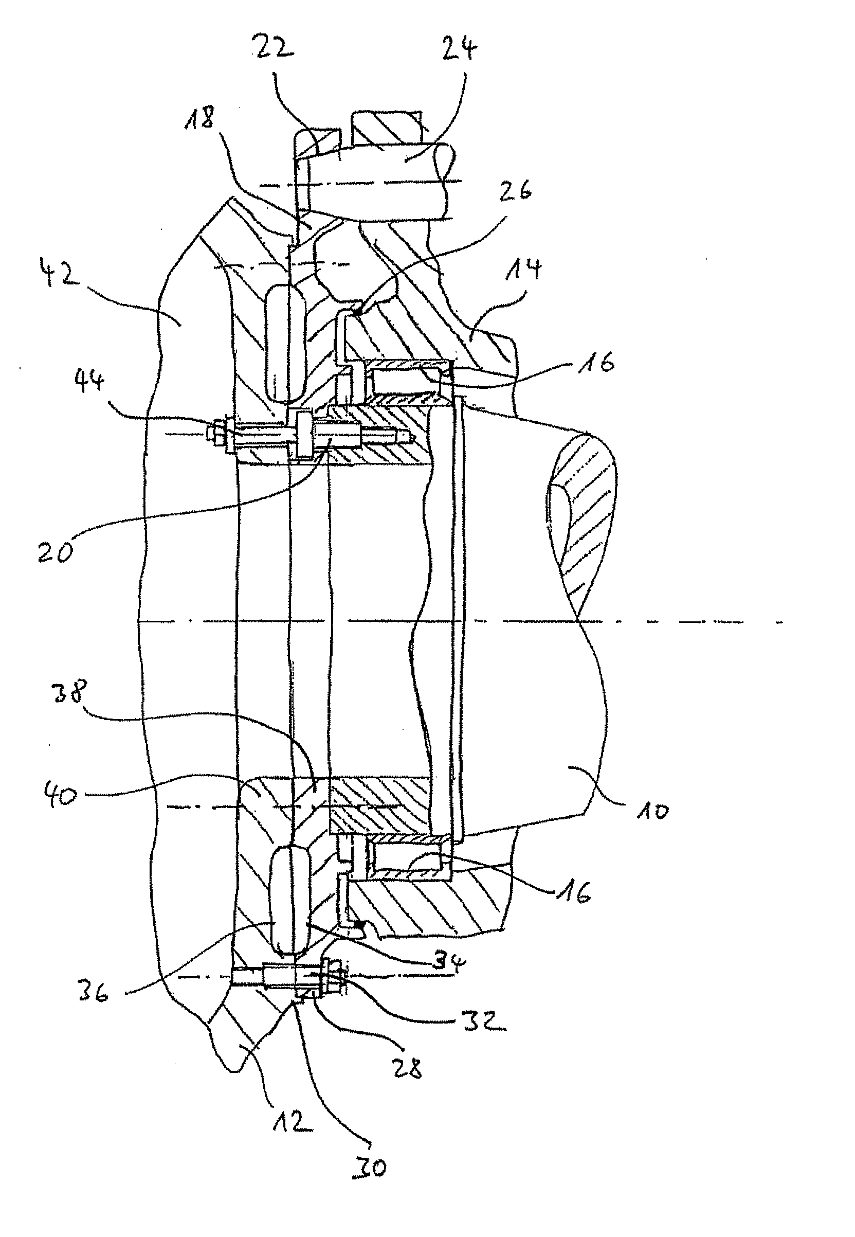
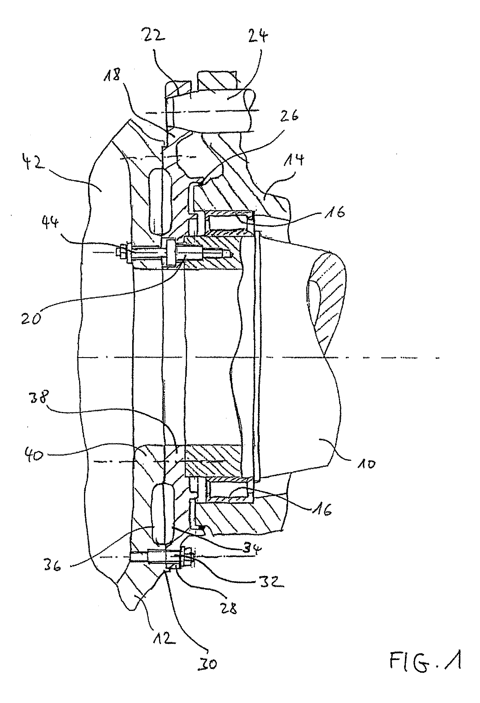
[0011]After the arrangement of the hub in the installation position, the preliminary connection of the hub with the bearing mounted rotor shaft takes place according to the present invention via screwing together the hub with the locking disk, starting from out the
machine housing of the wind energy plant. A secure installation of the rotor hub which hangs on a crane, for instance, is made possible through this. The preliminary screwing connects only the locking disk and the hub in particular. It serves as a remaining installation joint, so that the hub can be entered by operators from the inner side of the hub for the definite screwing. As a second step, the definite screwing of the hub on the rotor shaft and the locking disk takes place in a safe manner from the preliminarily attached and through this accessible rotor hub. In particular, the definite screwing connects only the rotor hub, the locking disk and the rotor shaft. It provides the attachment security of the hub on the shaft which is required in the operation of the plant.
[0012]By the present invention, screwing the rotor hub together with the rotor shaft is made possible via the locking disk, without having to enter the hub before a first attachment on the rotor shaft. Just with cylindrical rotor shafts or rotor shafts without marked attachment
flange, it is necessary to perform the definite screw joining between rotor hub and rotor shaft starting from out the rotor shaft. According to the present invention, this is made possible in a safe manner due to the preliminary connection. The industrial safety requirements are always maintained. All the wind loads occurring during the installation time are securely dissipated into the bearing housing and / or the
machine carrier via the rotor shaft, which is locked up against rotation. In this, the wind energy plant according to the present invention is distinguished through a compact and secure connection of the hub with the shaft.
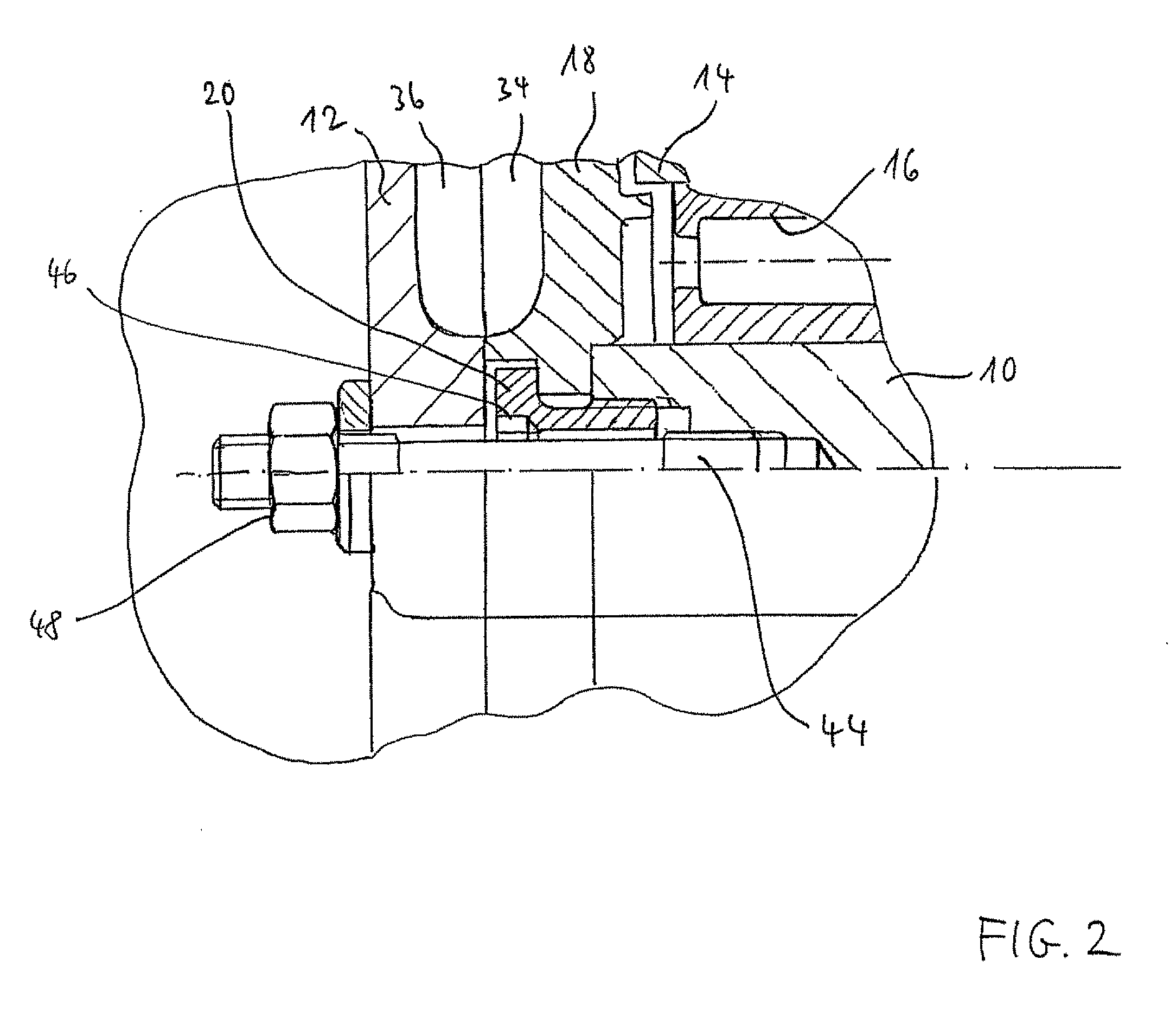
[0014]When using banjo bolts, it is also possible that the same have an internal thread, and that the definite screwing of the rotor hub with the locking disk and the rotor shaft takes place by studs which are screwed into the internal thread of the banjo bolts. Then, the studs may be screwed up in the banjo bolts only. For the definite screwing, no additional threaded bores have to be provided in the rotor shaft in addition to the threaded bores provided in the rotor shaft for screwing up the banjo bolts. The rotor shaft is secured only by screwing the studs into the banjo bolts. In cast parts, like rotor shafts, the load of internal threads may be limited due to the smaller strength. In order to increase the strength in the thread, so-called helicoil inserts are partly used, which increase the effective thread
diameter and thus increase the loading capacity of the thread in the cast part. A banjo bolt with internal and external thread takes over this functionality. Thus, with this embodiment, the
carrying capacity of the thread in the rotor shaft is increased, and a particularly secure connection is achieved. Again, even other screws, hexagon head cap screws for instance, can be used instead of the studs.
[0015]A particularly simple and compact connection of the locking disk with the rotor hub results when the locking disk has an attachment flange in its outer region, for attachment with a corresponding flange of the rotor hub. Thus, the rotor hub can have a corresponding flange. The attachment flanges can each have a planar
bearing surface. For the attachment, the attachment flange of the locking disk is made to sit closely on the corresponding planar
bearing surface of the attachment flange of the rotor hub. It is possible to arrange the bores of the locking disk in the attachment flange for preliminary attachment of the rotor hub. In this case, the locking disk has a (partial) circle of screws situated on the exterior, via which the preliminary screwing of the rotor hub takes place.
[0016]According to an extension related to this, the attachment flange is connected via stiffening ribs with an inner attachment flange, provided concentrically to the attachment flange and having a plurality of bores for definitely screwing together the rotor hub with the locking disk and the rotor shaft. The inner attachment flange has also a planar
bearing surface, through which it is made to sit closely to a corresponding planar bearing surface of the rotor hub for the installation. The rotor hub may also have corresponding stiffening ribs for the connection of its attachment flange with the remaining parts of the hub. The stiffening ribs can end up in a plane with the bearing surfaces of the respectively attachment flange, or they can end up offset back with respect to this bearing surface. By the large planar site joint between rotor hub and locking disk for the preliminary attachment, in connection with stiffening ribs in the locking disk and / or the flange surface of the rotor hub, there results a particularly thin-walled and thus material saving and through this lightweight and cost-saving construction on the one hand. On the other hand, the specially formed flange regions of the locking disk and when necessary of the rotor hub form a hollow section with stiffening ribs after tensioning the outside situated preliminary screwing and the inside situated screwing between rotor hub, locking disk and rotor shaft. The hollow section is generated by the screwing of two shells via one partial circle on the outside and another one on the inside, and it forms a stiff connection construction arranged at the front side of the rotor hub with small wall thickness. Through this circumferential hollow section, a particularly stiff connection is achieved.

