Method for Supplying Fuel Gas To a Gas Chamber of a Fuel Cell and Fuel Cell

Inactive Publication Date: 2010-02-04
SIEMENS ENERGY GLOBAL GMBH & CO KG
View PDF4 Cites 9 Cited by
  • Summary
  • Abstract
  • Description
  • Claims
  • Application Information

AI Technical Summary

Benefits of technology

[0018]Preferably the fuel cell includes a device for measuring a pressure difference between the gas chambers of the fuel cell and for setting the pressure increase velocity in at least one of the two gas chambers as a function of said pressure difference such that a defined limit value for the pressure difference is not

Problems solved by technology

Because of the large cross-section, however, after the valves are opened at the time of switching on the gas supply, t

Method used


Image

  • Method for Supplying Fuel Gas To a Gas Chamber of a Fuel Cell and Fuel Cell
  • Method for Supplying Fuel Gas To a Gas Chamber of a Fuel Cell and Fuel Cell
  • Method for Supplying Fuel Gas To a Gas Chamber of a Fuel Cell and Fuel Cell

Examples


Embodiment Construction

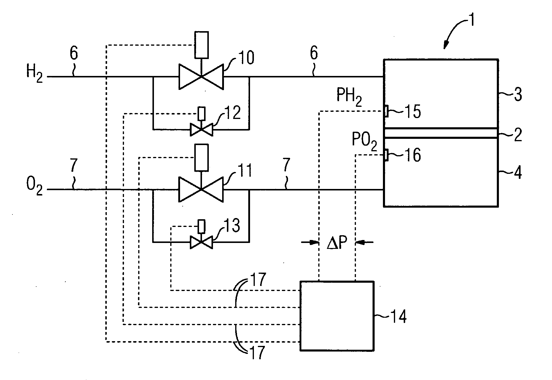
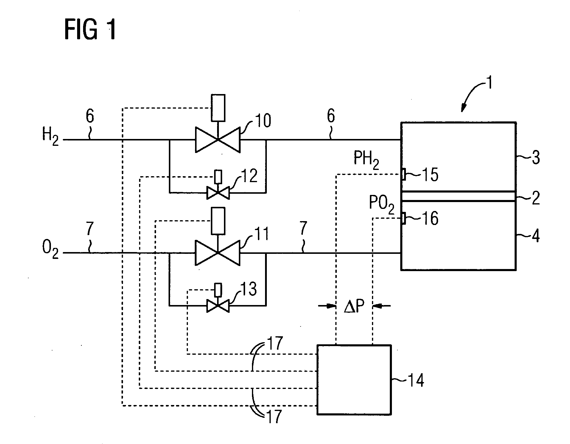
[0022]FIG. 1 is a schematic diagram depicting a fuel cell 1 of a fuel cell system that is not shown in further detail. The fuel cell 1 has a cell membrane 2 having an adjoining anode gas chamber 3 on one side of the cell membrane and an adjoining cathode gas chamber 4 on the other side of the cell membrane 2. Hydrogen H2 is supplied to the anode gas chamber 3 via a gas supply line 6 and oxygen O2 is supplied to the cathode gas chamber 4 via a gas supply line 7. Connected into the gas supply line 6 is a valve 10 having a suitably large cross-section for supplying gas to the anode gas chamber 3 during normal operation of the fuel cell 1. The entire gas volume flow required for operation at full load can flow via the valve 10 with a minimum pressure drop.

[0023]Additionally connected into the gas supply line 6 in parallel with the valve 10 is a valve 12 having a smaller flow cross-section. This latter valve serves as a starting or bypass valve for the fuel gas supply at the time the fue...


PUM


Abstract

Mechanical stresses of the membrane of a fuel cell can be reduced by virtue of the fact that the supply of feed gas to a gas chamber of the fuel cell takes places, initially, by means of a first pressure increasing speed and then by means of a second pressure increasing speed. The first pressure increasing speed is slower than the second pressure increasing speed. Pressure surges are prevented in the membrane due to the lower pressure increasing speed in the first phase of the gas supply, and as a result, the life span of the membrane is increased.

Description

CROSS REFERENCE TO RELATED APPLICATIONS[0001]This application is the U.S. National Stage of International Application No. PCT / EP2006 / 063430, filed Jun. 22, 2006 and claims the benefit thereof. The International Application claims the benefits of European application No. 05013970.8 filed Jun. 28, 2005, both of the applications are incorporated by reference herein in their entirety.FIELD OF INVENTION[0002]The invention relates to a method for supplying fuel gas to a gas chamber of a fuel cell and also a fuel cell.BACKGROUND OF THE INVENTION[0003]In a fuel cell, hydrogen and oxygen are typically combined to generate energy and heat in an electrochemical reaction, with water being produced as the sole byproduct. To that end, the hydrogen is ducted into an anode gas chamber and the oxygen into a cathode gas chamber of the fuel cell. The hydrogen can be fed to the anode gas chamber either as pure hydrogen or as a hydrogenous fuel gas. The oxygen can be supplied to the cathode gas chamber ...

Claims


Application Information

Patent Timeline
IPC IPC(8): H01M8/04H01M8/00
CPCH01M8/04089H01M8/04104H01M8/04223H01M8/04395Y02E60/50H01M8/04753H01M8/04783H01M2008/1095H01M8/04432H01M8/04225H01M8/04302H01M8/04
Inventor COERLIN, DETLEVCOERLIN, HERDITH GRETE GABRIELESTUHLER, WALTERVOITLEIN, OTTMAR
Owner SIEMENS ENERGY GLOBAL GMBH & CO KG
Why Eureka
Try Eureka