Engine boost control for multi-fuel engine

a multi-fuel engine and boost control technology, applied in the direction of electrical control, process and machine control, etc., can solve the problems of reducing the available boost, reducing the engine output torque, and reducing the charge cooling effect of direct injection, so as to reduce the amount of reduction, operate with a greater amount of boost, and reduce the effect of heat vaporization

Inactive Publication Date: 2010-02-04
FORD GLOBAL TECH LLC
View PDF14 Cites 32 Cited by
  • Summary
  • Abstract
  • Description
  • Claims
  • Application Information

AI Technical Summary

Benefits of technology

[0005]To address these and other issues, the inventors herein have provided a method for controlling an internal combustion engine to deliver a desired engine output. The method comprises: delivering a first fuel blend from a first fuel tank to the engine; delivering a second fuel blend from a second fuel tank to the engine, the proportion of said second fuel blend delivered to the engine to said first blend delivered to the engine being related to the desired engine output; transferring said first fuel blend from said first fuel tank to said second fuel tank to prevent an amount of said first fuel blend and said second fuel blend in said second fuel tank from falling below a predetermined level; and boosting air delivered to the engine, the amount of boosting being related to latent heat of vaporization or alcohol concentration of said second fuel blend delivered to the engine.
[0006]In this way, fuel (albeit possibly with a lower heat of vaporization) is available for direct injection even when the primary direct injection fuel (e.g. ethanol) is exhausted prior to the other fuels residing on-board the vehicle. In this way, it is possible to at least obtain charge cooling benefits of direct injection, and therefore the engine may be operated with a greater amount of boost than if using port injected gaso...

Problems solved by technology

In one particular example, if the ethanol fuel is used up before the gasoline fuel, the engine may experience increased knock at higher boost levels.
For example, such an approach results in significantly reduced available boost, and thus engine o...

Method used


Image

  • Engine boost control for multi-fuel engine
  • Engine boost control for multi-fuel engine
  • Engine boost control for multi-fuel engine

Examples


Embodiment Construction

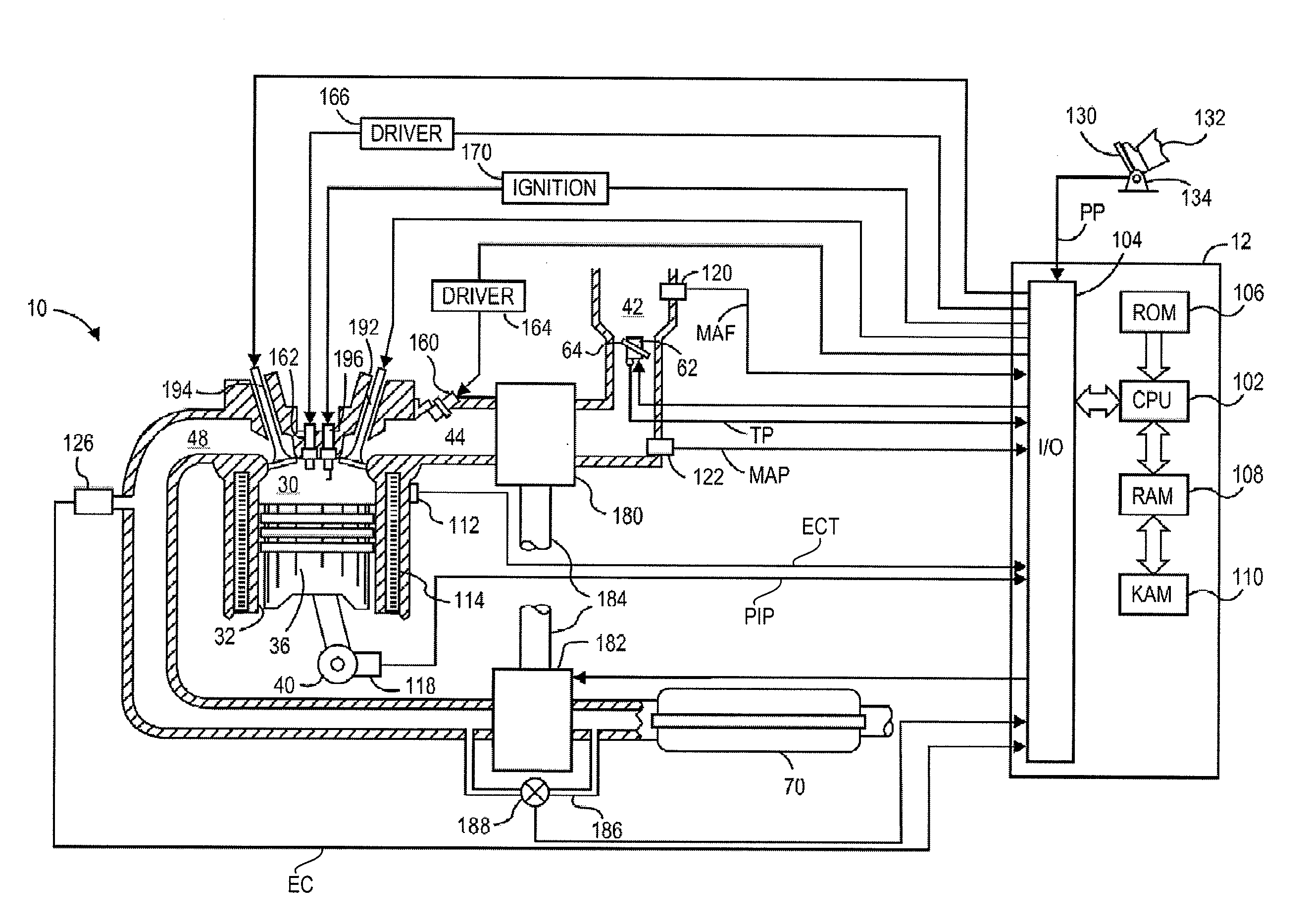
[0018]The following disclosure presents a fuel delivery system that may be configured to deliver one or more different fuels to a fuel burning engine. These fuels may include liquid fuels, gaseous fuels, or combinations of liquid and gaseous fuels. In some embodiments, the fuel burning engine may form an engine system of a vehicle, including vehicles powered exclusively by fuel and hybrid electric vehicles (HEV), among others. While a fuel burning engine is described in the context of an internal combustion engine for a vehicle, it should be appreciated that the various fuel delivery approaches described herein are not limited to the disclosed engine configurations or applications, but may be used in other suitable configurations or applications where appropriate.

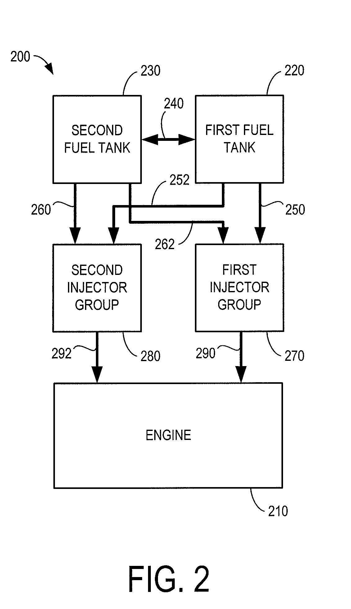
[0019]In some embodiments, a fuel delivery system may be operated to deliver to an engine, two or more fuels having different fuel compositions from two or more different fuel sources. As a non-limiting example, a first fue...


PUM


Abstract

A fuel delivery system for an internal combustion engine and a method of operating the fuel delivery system is described. As one example, the method includes delivering a first fuel blend from a first fuel tank to the engine; delivering a second fuel blend from a second fuel tank to the engine, the proportion of said second fuel blend delivered to the engine to said first fuel blend delivered to the engine being related to the desired engine output; transferring said first fuel blend from said first fuel tank to said second fuel tank to prevent an amount of said first fuel blend and said second fuel blend in said second fuel tank from falling below a predetermined level; and boosting air delivered to the engine, the amount of boosting being related to latent heat of vaporization of said second fuel blend delivered to the engine.

Description

BACKGROUND AND SUMMARY[0001]Various fuel delivery systems may be used to provide a desired amount of fuel to an engine for combustion. Some fuel delivery systems utilize port fuel injectors to deliver fuel to each of cylinder of the engine. Other fuel delivery systems utilize direct fuel injectors to deliver fuel directly to each cylinder of the engine. Still other engines have been described that utilize both port and direct fuel injectors for each cylinder to deliver different types of fuel to the engine.[0002]One example is described in the papers titled “Calculations of Knock Suppression in Highly Turbocharged Gasoline / Ethanol Engines Using Direct Ethanol Injection” and “Direct Injection Ethanol Boosted Gasoline Engine: Biofuel Leveraging for Cost Effective Reduction of Oil Dependence and CO2 Emissions” by Heywood et al. Specifically, the Heywood et al. papers describe directly injecting ethanol into the cylinders to improve charge cooling effects, while relying on port injected...

Claims


Application Information

Patent Timeline
IPC IPC(8): F02D37/00F02D33/02
CPCF02D19/0684F02D41/0025F02D41/3094F02D2200/0611F02D2200/0612F02D19/081F02M37/0088Y02T10/36F02D19/0655F02D19/0665F02M37/0064Y02T10/30
Inventor LIPPA, ALLAN J.LEWIS, DONALD J.
Owner FORD GLOBAL TECH LLC
Why Eureka
Try Eureka