System and method for solar energy capture

a solar energy and energy system technology, applied in the field of solar energy systems and methods, can solve the problems of thermal management difficult, high-efficiency pv cells remain expensive, and energy systems employing both pv cell(s) and solar concentration devices

Inactive Publication Date: 2010-02-11
RGT UNIV OF CALIFORNIA
View PDF16 Cites 32 Cited by
  • Summary
  • Abstract
  • Description
  • Claims
  • Application Information

AI Technical Summary

Benefits of technology

[0010]In at least some such embodiments, a multiband solar concentrator simultaneously provides moderate (10×) aperture concentration and wavelength splitting. The mirror devices divide the incident spectrum into visible and near-infrared / infrared wavelengths that propagate into first PV cell(s) and second PV cell(s) that are respectively optimized for each spectral band. Individual light paths are incident on a common printed circuit board with interleaved PV cells for each spectral band. Reflective sidewalls resembling a cone concentrator aid in the confinement of light from wide angles as they are directed and concentrated onto each individual PV cell. Each element is designed for concatenation into an array. A large area solar cell can be constructed from many small cells located side by side in a 1D or 2D arrangement.

Problems solved by technology

While much effort is being focused upon developing more efficient photovoltaic (PV) cells that can generate greater amounts of electrical energy based upon a given amount of solar radiation directed upon those cells, high efficiency PV cells nevertheless remain expensive.
While potentially providing such advantages, existing solar energy systems employing both PV cell(s) and solar concentration devices have certain disadvantages as well.
The use of such adjacent, orthogonal PV cells makes thermal management difficult, reduces the upward-facing fill-factor and also increases production costs.
However, for such designs, the PV cells still must be placed orthogonal to one another leading to problems in packaging and thermal management.

Method used


Image

  • System and method for solar energy capture
  • System and method for solar energy capture
  • System and method for solar energy capture

Examples


Embodiment Construction

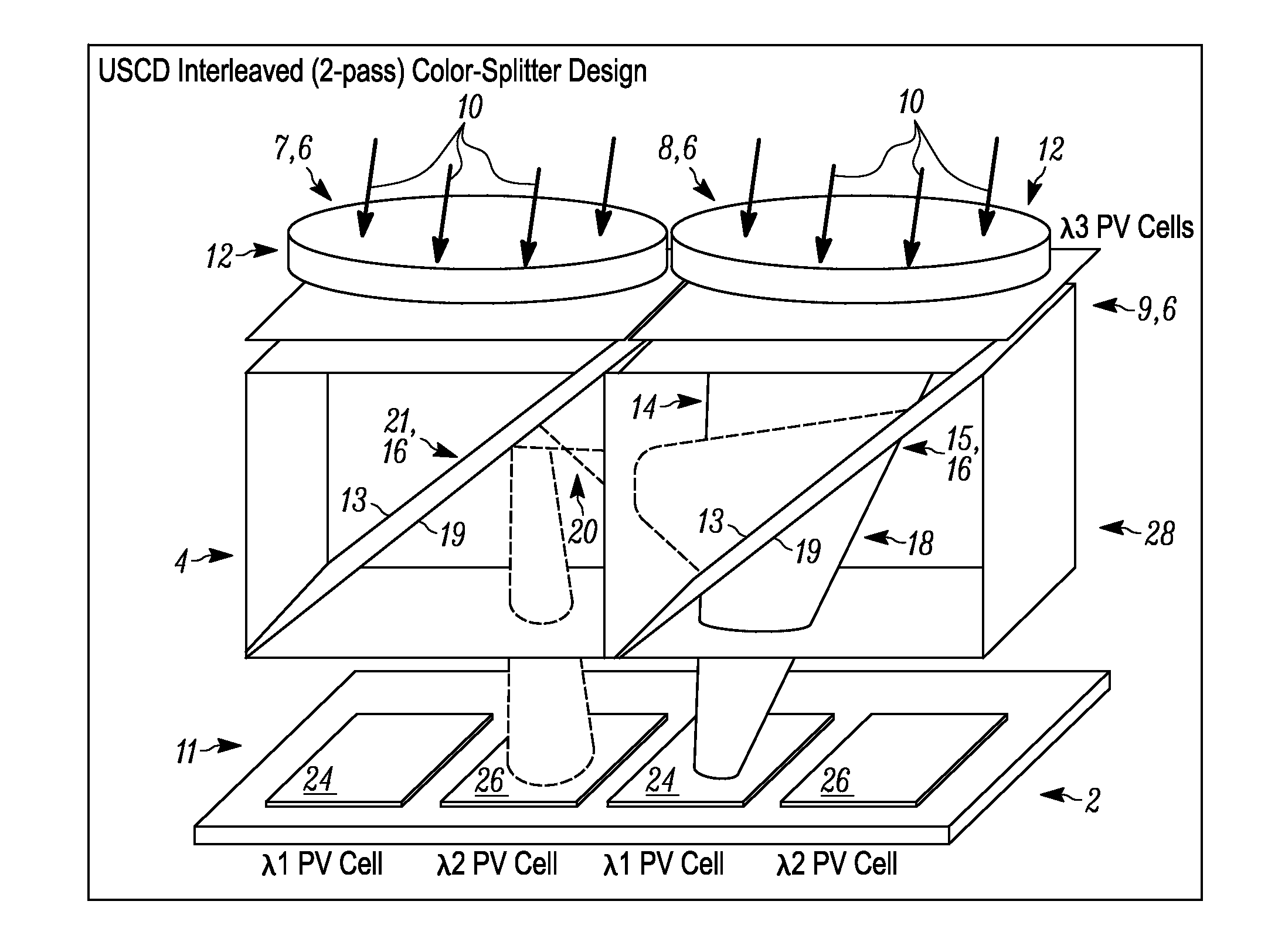
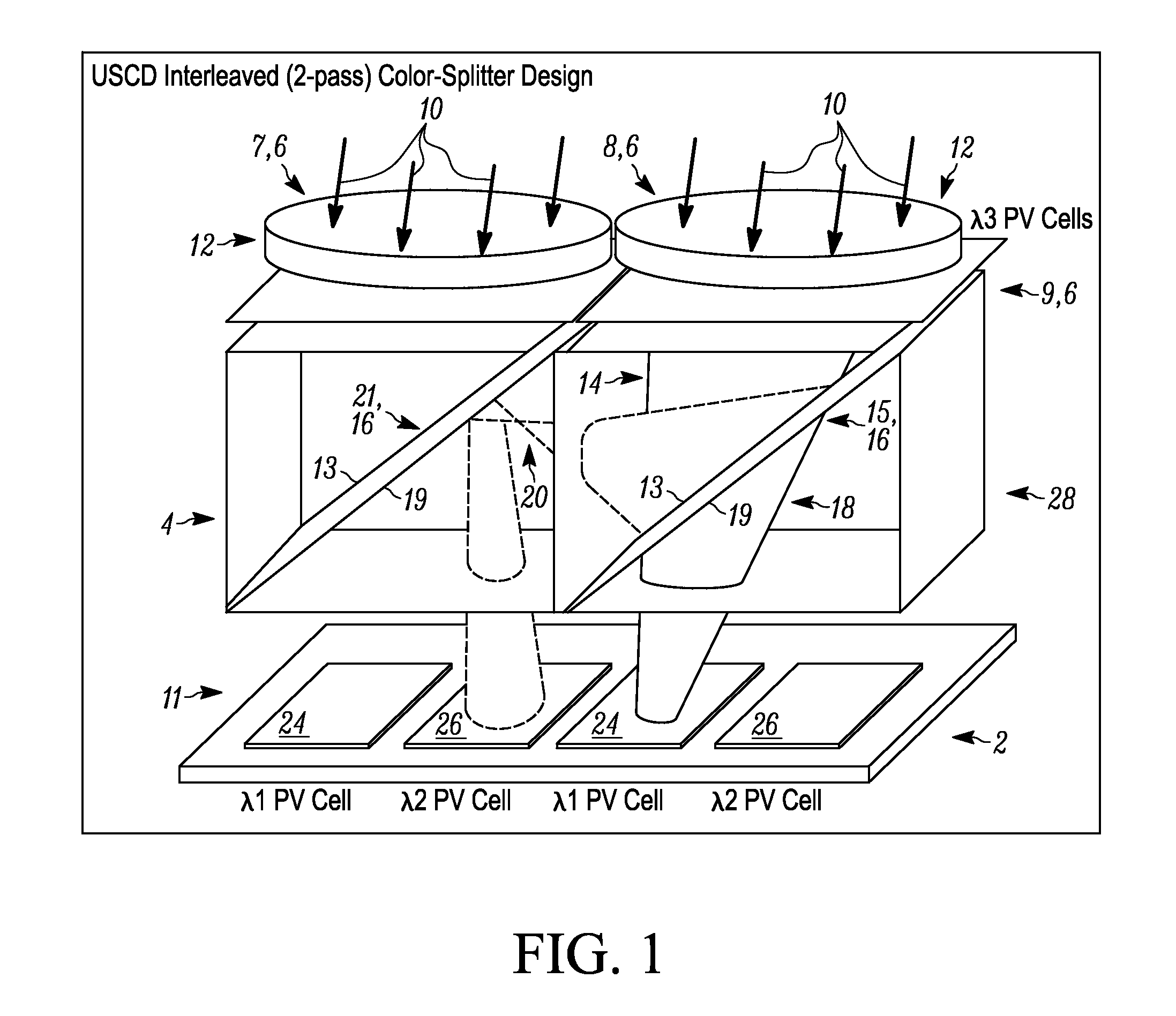
[0018]Referring to FIG. 1, a schematic, perspective view is provided showing components of an exemplary solar energy device 2 allowing for both concentration of incoming light as well as separation of such light into light portions within different wavelength ranges that are in turn directed to different types of PV cells, respectively, in accordance with at least one embodiment of the present invention. As shown, the solar energy device 2 includes a solar concentration section 4 that includes multiple solar concentrators 6, a first 8 of which is shown completely, and second 7 and third 9 of which are shown only partly. Additionally, the solar energy device 2 also includes a photovoltaic (PV) cell section 11 that includes multiple PV cells arranged in a coplanar manner, along a side of the solar concentration section 4 that is generally opposite to a side at which incoming light is incident upon that section and upon the overall solar energy device 2.

[0019]As illustrated schematical...


PUM


Abstract

A system and a method for capturing solar energy are disclosed herein. In at least one embodiment, the method includes receiving light at a plurality of lenses, communicating the light from respective ones of the plurality of lenses toward respective ones of a plurality of dichroic mirrors, and transmitting respective first portions of the light through the respective ones of the dichroic mirrors toward respective first photovoltaic cells. The method also includes reflecting respective second portions of the light off of the respective ones of the dichroic mirrors toward respective adjacent ones of the dichroic mirrors, where the first portions are within a first wavelength range and the second portions are within a second wavelength range, and reflecting the respective second portions of the light off of the respective adjacent ones of the dichroic mirrors toward respective second photovoltaic cells.

Description

CROSS-REFERENCE TO RELATED APPLICATIONS[0001]This application claims the benefit of U.S. Provisional Patent Application No. 61 / 088,069, entitled “System and Method for Solar Energy Capture” filed on Aug. 12, 2008, which is incorporated herein by reference, and also claims priority to U.S. Provisional Application No. 61 / 087,447, entitled “System and Method for Solar Energy Capture” filed on Aug. 8, 2008, which is hereby incorporated by reference herein.FIELD OF THE INVENTION[0002]The present invention relates to solar energy systems and methods and, more particularly, to systems and methods for capturing solar energy that operate at least in part by way of concentrating received light prior to conversion of the light into electrical or other power.BACKGROUND OF THE INVENTION[0003]Solar energy systems are of greatly increased interest due to rising energy demands worldwide and consequent rising prices for existing energy resources, especially petroleum resources. While much effort is ...

Claims


Application Information

Patent Timeline
Patent Type & Authority Applications(United States)
IPC IPC(8): H01L31/052
CPCH01L31/0232H01L31/0547H01L31/0543Y02E10/52H01L31/02325
Inventor FORD, JOSEPHKARP, JASON
Owner RGT UNIV OF CALIFORNIA
Why Eureka
Try Eureka