Image forming apparatus

An image and toner image technology, applied in the field of image forming devices, can solve problems such as inability to fully remove charges, premature deterioration of photosensitive drums, and influence on printed images

Inactive Publication Date: 2012-03-14
CANON KK
View PDF5 Cites 7 Cited by
  • Summary
  • Abstract
  • Description
  • Claims
  • Application Information

AI Technical Summary

Problems solved by technology

However, if the amount of laser light is always increased in operations including printing operations, the charge of the latent image formed on the photosensitive drum cannot be sufficiently removed
This can adversely affect the next printed image or cause premature deterioration in the photosensitive drum

Method used


Image

  • Image forming apparatus
  • Image forming apparatus
  • Image forming apparatus

Examples


no. 1 example

[0040] 【Overall layout

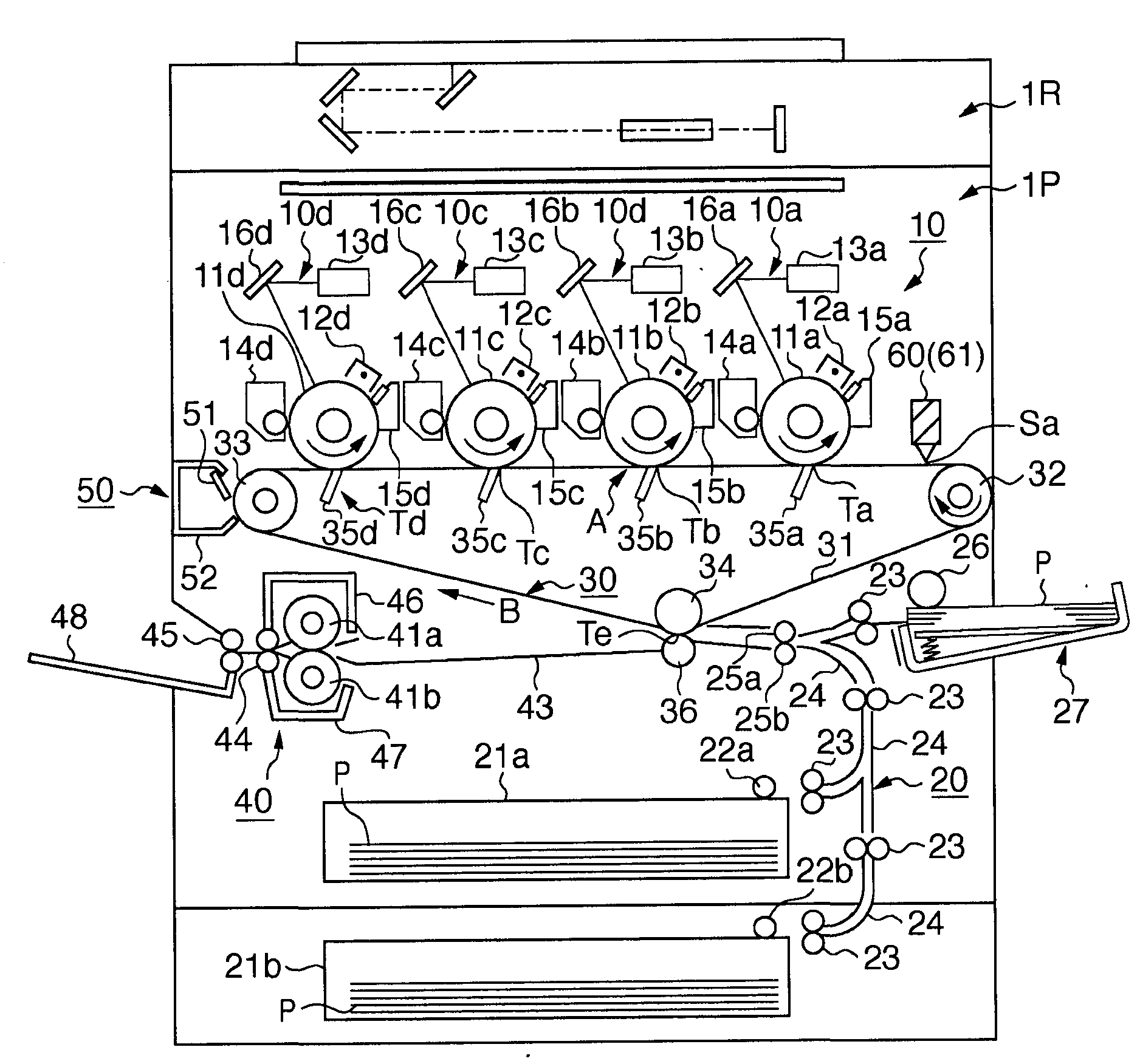
[0041] figure 1 is a schematic sectional view showing the general arrangement of an electrophotographic color copier which is an embodiment of an image forming apparatus according to the present invention. The electrophotographic color copier according to the present embodiment is a color image output device including a plurality of image forming units arranged side by side and using an intermediate transfer mechanism, to which the present invention is expected to be particularly effectively applied.

[0042] In this embodiment, an electrophotographic color copier includes an image reading unit 1R and an image output unit 1P. The image reading unit 1R optically reads a document image, converts it into an electrical signal, and sends it to the image output unit 1P. The image output unit 1P includes four image forming units 10 (ie, 10 a , 10 b , 10 c , and 10 d ), a paper feeding unit 20 , an intermediate transfer unit 30 , a fixing unit 40 , and a cl...

no. 2 example

[0104] In the first embodiment, when the amount of laser light is set independently for the printing operation and registration correction, the delay time of the detection signal from the BD sensor 314 with respect to the synchronization of the main scanning of the laser beam can be different from each other. This delay time is the delay time from the time when the laser beam strikes the BD sensor 314 to the time when the BD sensor 314 outputs the main scanning start signal S12. This delay time difference can cause a shift in write timing in the main scanning direction at the time of printing.

[0105] Figure 14A It is shown that the delay time T of the BD sensor 314 remains constant even when the laser light amount L1 at the time of registration correction and the laser light amount L2 at the time of printing are respectively set to different light amounts. In such a case, the above shift does not occur in the write timing in the main scanning direction.

[0106] However, ...


PUM


Abstract

An image forming apparatus comprises: an exposure unit configured to irradiate each of a plurality of photosensitive members with a light beam, a light amount control unit configured to control a light amount of the light beam, a plurality of developing units configured to develop electrostatic latent images, formed on the plurality of photosensitive members by exposure with the light beams, and a transfer unit configured to transfer toner images formed on the plurality of photosensitive members onto an image carrier; a pattern forming unit configured to control the image forming unit to form, a misalignment detection pattern for detecting a relative misalignment between the toner images transferred onto the image carrier; a pattern reading unit configured to read the misalignment detection pattern; and a correction unit configured to correct the relative misalignment between the toner images based on the reading result obtained by the pattern reading unit.

Description

technical field [0001] The present invention relates to an image forming apparatus, and more particularly, to a technique for correcting misregistration between individual colors in an electrophotographic color image forming apparatus. Background technique [0002] Conventionally, there has been proposed, for example, a multicolor image forming apparatus which includes a plurality of image forming units and which can form a color image in the following procedure. Each image forming unit applies a laser beam to a drum-shaped electrophotographic photoreceptor (ie, a photosensitive drum) as an image carrier. Each unit forms an electrostatic latent image on a photosensitive drum through an electrophotographic process. The developing device develops the electrostatic latent image and makes it a visible image (toner image). The transfer unit transfers the toner images formed on the photosensitive drums by the respective image forming units in multiple layers onto a transfer mate...

Claims


Application Information

Patent Timeline
Patent Type & Authority Applications(China)
IPC IPC(8): G03G15/00G03G15/01
CPCG03G15/0131G03G15/0189G03G15/5058G03G2215/0129G03G2215/0161
Inventor 高桥克实铃木慎也
Owner CANON KK
Why Eureka
Try Eureka