Slide rail structure

a technology of sliding rails and supports, applied in the direction of support structure mounting, electrical apparatus construction details, furniture parts, etc., can solve the problem of unable to install, and achieve the effect of avoiding the turnover of computer cases and small width

Active Publication Date: 2010-02-11
INVENTEC CORP
View PDF30 Cites 9 Cited by
  • Summary
  • Abstract
  • Description
  • Claims
  • Application Information

AI Technical Summary

Benefits of technology

[0021]In the slide rail structure of the present invention, the carrying part of the second slide rail carries the computer case, and the computer case can be slid on the carrying part, so that assembling a slide rail on the computer case is unnecessary. Therefore, a space between the computer case and the rack, which is originally used for assembling the slide rail to the computer case can be saved. Thus, the slide rail structure of the present invention can be allocated to a space with a relatively small width. Moreover, in the slide rail structure of the present invention, the rail part of the third slide rail is interfered with the supporting member on the computer case. Therefore, turnover of the computer case can be avoided.

Problems solved by technology

However, the inner slide rail has to be assembled to the side of the computer first.
Therefore, if the computer having a relatively great width is assembled to the rack, it probably cannot be installed due to excessive widths of the inner and outer slide rails.

Method used


Image

  • Slide rail structure
  • Slide rail structure
  • Slide rail structure

Examples


Embodiment Construction

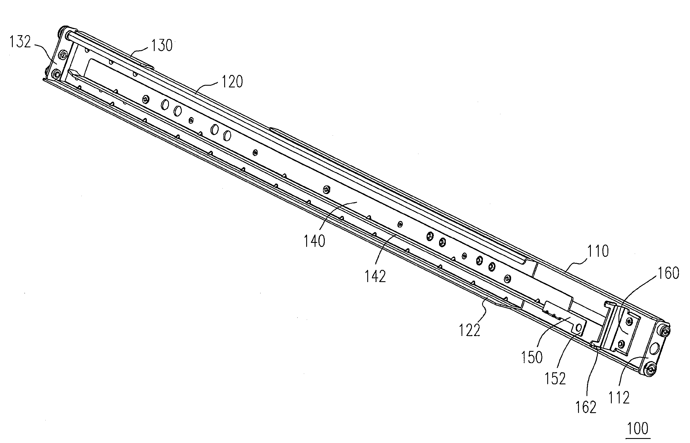
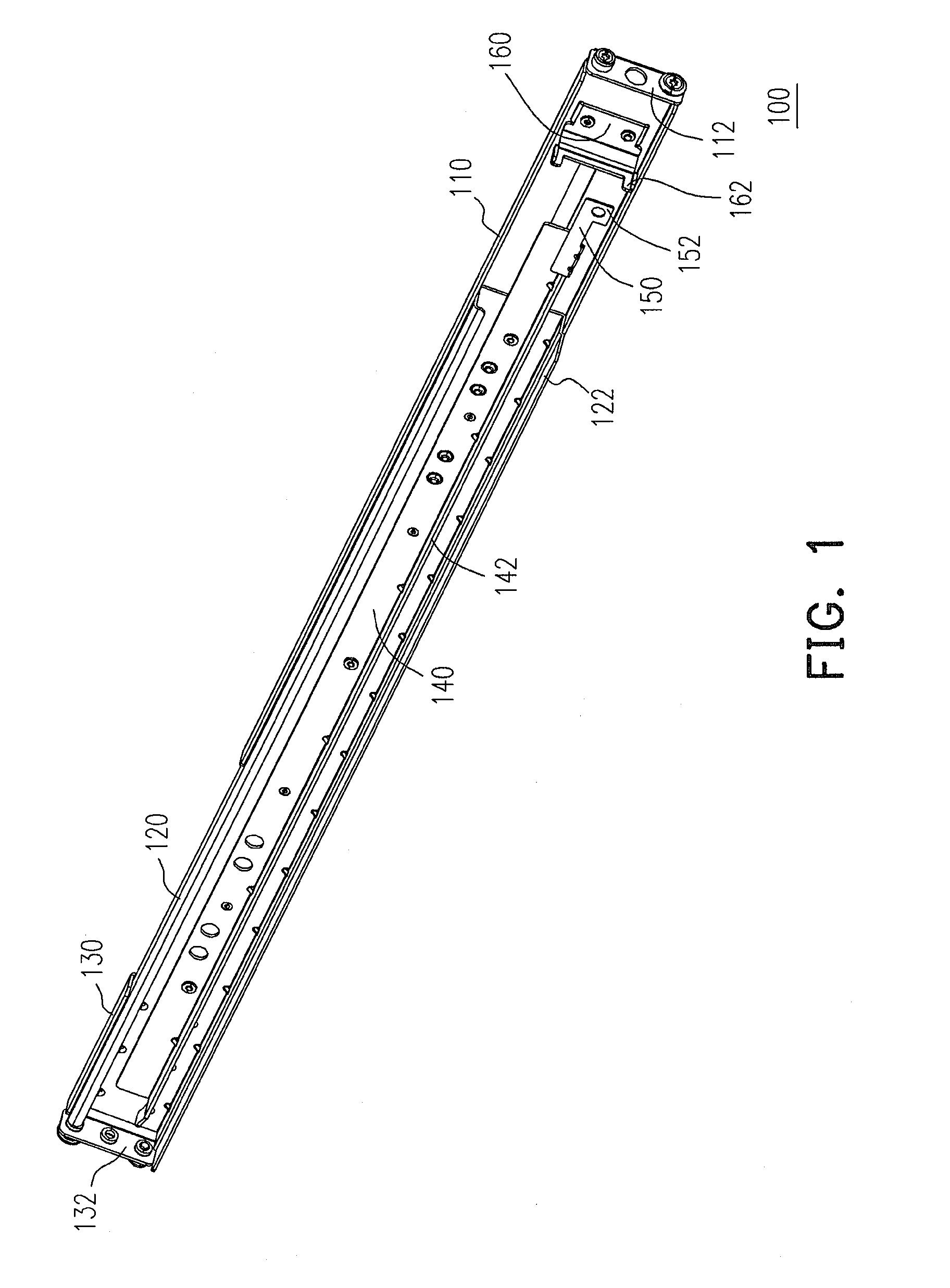
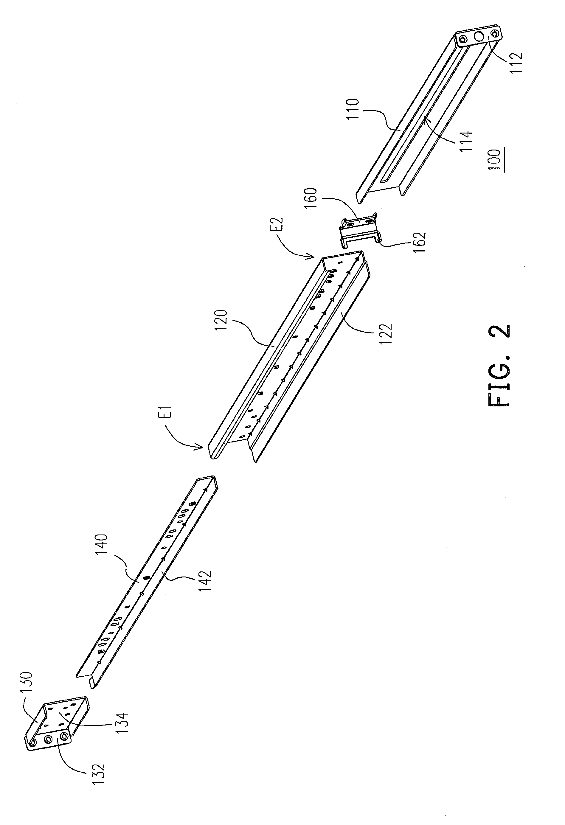
[0027]FIG. 1 is a schematic diagram of a slide rail structure according to an embodiment of the present invention. FIG. 2 is an exploded view of FIG. 1. Referring to FIG. 1 and FIG. 2, the slide rail structure 100 is disposed between a computer case (not shown) and a rack (not shown). The slide rail structure 100 includes a first slide rail 110 and a second slide rail 120. In the present embodiment, the second slide rail 120 is nested in the first slide rail 110. Though in the present embodiment, only a single slide rail structure 100 is described, in an actual application, the slide rail structure 100 can be disposed at both sides of the computer case and the rack in a pair, and a length between two sides of the rack is a width of the rack.

[0028]The first slide rail 110 is fixed to the rack. For example, the first slide rail 110 has a fixing part 112, and the fixing part 112 is fixed to a rear end of the rack. The second slide rail 120 has a first end E1, a second end E2 and a carr...


PUM


Abstract

A slide rail structure is provided. The slide rail structure is disposed between a computer case and a rack, and includes a first slide rail and a second slide rail. The first slide rail is fixed to the rack. The second slide rail has a first end, a second end and a carrying part. The second slide rail is fixed to the rack via the first end, and is connected to the first slide rail via the second end. The carrying part contacts a bottom plate of the computer case for sliding the computer case on the carrying part.

Description

CROSS-REFERENCE TO RELATED APPLICATION[0001]This application claims the priority benefit of P.R.C. patent application serial no. 200810145471.6, filed on Aug. 8, 2008. The entirety of the above-mentioned patent application is hereby incorporated by reference herein and made a part of specification.BACKGROUND OF THE INVENTION[0002]1. Field of the Invention[0003]The present invention relates to a slide rail structure. More particularly, the present invention relates to a slide rail structure of a computer appliance.[0004]2. Description of Related Art[0005]Generally, computers are grouped into personal computers, servers and super computers according to application degrees thereof. The personal computer generally applies one or two processors for processing administrative business of a general enterprise or multimedia related information. If complicated works or large amount of data is required to be processed, the server is generally applied, in which the server having two to four pro...

Claims


Application Information

Patent Timeline
Patent Type & Authority Applications(United States)
IPC IPC(8): A47F7/00
CPCH05K7/1489
Inventor DU, LIAN-CHANGYANG, SHOU-JEN
Owner INVENTEC CORP
Why Eureka
Try Eureka