Retarder slip control

a technology of retarder and slip control, which is applied in the direction of braking system, braking components, transportation and packaging, etc., can solve the problems of reducing the braking effect, locking the drive axle(s), and simply feeling uncomfortable to the driver, so as to achieve efficient braking and eliminate the uncomfortable braking

Inactive Publication Date: 2010-02-11
VOLVO LASTVAGNAR AB
View PDF6 Cites 4 Cited by
  • Summary
  • Abstract
  • Description
  • Claims
  • Application Information

AI Technical Summary

Benefits of technology

[0045]When the foundation brakes are activated in order to compensate for the loss or significant reduction of braking effect of the auxiliary brakes, it is particularly advantageous if this activation is initiated before or exactly when the auxiliary brakes disengage. This will eliminate the uncomfortable “slip” of braking effect since there is not the usual period of time before the foundation brakes are engaged.
[0046]According to the method of the present invention the calculated required braking effect may be applied to the foundation brakes either per axle or per individual wheel. The appliance may in either case be applied in order to obtain the most efficient braking of the vehicle or vehicle combination.

Problems solved by technology

However, it has been experienced that a sudden loss or significant reduction of the braking effect from the auxiliary brakes may occur in certain situations, which can lead to dangerous and uncontrollable situations, which again potentially can result in an accident.
One such situation is locking of the drive axle(s), which may occur if the vehicle is used under conditions where the friction force between the road surface and the tyres of the drive axle(s) is too low for grip.
Aside from the potentially dangerous aspect of that situation (due to the loss of braking force), it may also simply feel uncomfortable to the driver when this sudden “slip” of the brakes occurs.

Method used


Image

  • Retarder slip control
  • Retarder slip control
  • Retarder slip control

Examples


Embodiment Construction

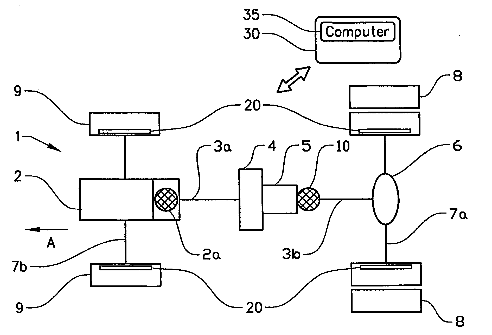
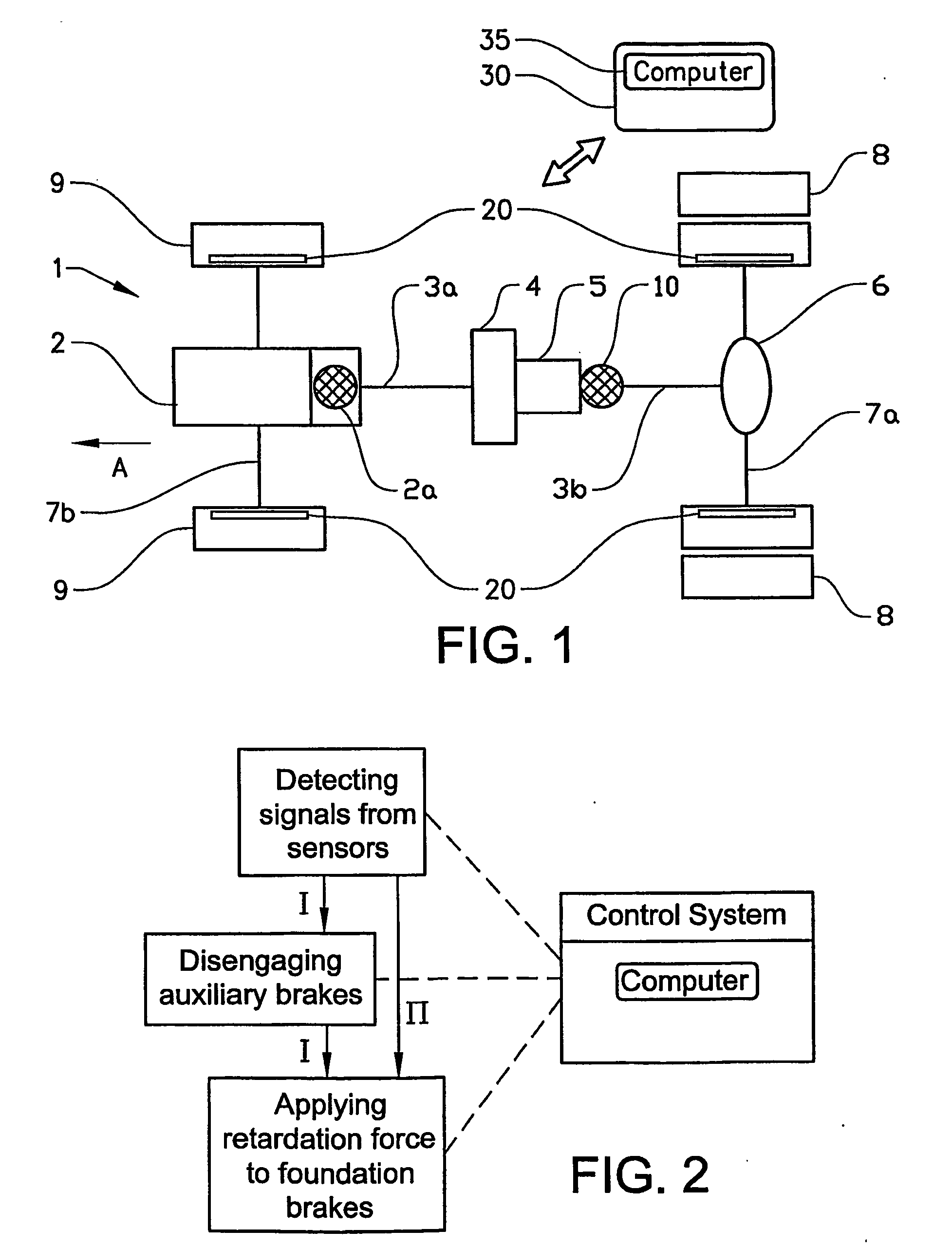
[0050]FIG. 1 schematically shows the driveline 1 of a typical heavy-duty motor vehicle pointing towards a normal driving direction as indicated by the arrow A. The driveline 1 comprises an internal combustion engine 2, a crankshaft 3a and a propeller shaft 3b, a transmission consisting of comprising a clutch device 4 and a gearbox 5, a final gear (or differential) 6, a drive axle 7a and a front axle 7b, non-driven wheels 9 and driving wheels 8. The clutch 4 can e.g. be a dry disk clutch or a hydraulic clutch connected to a gearbox 5 in a manner known to the skilled person. The gearbox 5 may be a manual or automatic gearbox.

[0051]The gearbox 5 is coupled together with the propeller shaft 3b, which, via a final gear / differential 6 and drive axle 7 known to the skilled person, drives the driving wheels 8 of the vehicle. In this example, a vehicle with only one front and rear axle is shown, but vehicles with more front and rear axles, driven and / or non-driven, are of course also possibl...


PUM


Abstract

A motor vehicle fitted with a control system for applying braking effect to foundation brakes acting on each wheel of the vehicle, when the braking effect provided by auxiliary brakes, acting on the driven wheels, is lost or significantly reduced is described. Sudden loss of auxiliary brake force can be felt as very bad drivability of the vehicle, a situation that typically occurs in case of low friction between road and tires or if the auxiliary brakes are down controlled to avoid engine stop. By use of a control system, these situations can be avoided. The control system includes a sensor, and a computer for computing and applying the braking effect to the foundation brakes to compensate for the loss of auxiliary braking force. Disclosed is also a method for applying braking effect to the foundation brakes of a motor vehicle.

Description

BACKGROUND AND SUMMARY[0001]Generally, the present invention relates to improvements in drivability and safety in motor vehicles having foundation brakes acting on at least some of the wheels of the vehicle and auxiliary brakes acting on the driven wheels of the vehicle. In particular, the invention relates to a control system and a method of applying and controlling the retardation force between the braking devices.BACKGROUND OF THE INVENTION[0002]In connection with heavy-duty vehicles, such as trucks, buses and construction-site machinery, it is well known to provide auxiliary brakes as a supplement to the service brakes of the vehicle, in the following designated foundation brakes and to increase the available braking power. This is typically done in order to increase the life time of the foundation brakes and to increase the available braking force, since these are otherwise exposed to significant wear due to the heavy loads on the vehicle, especially when driving down steep gra...

Claims


Application Information

Patent Timeline
Patent Type & Authority Applications(United States)
IPC IPC(8): B60T8/88B60TB60T8/00B60T10/02B60T17/22
CPCB60T8/00B60T17/221B60T10/02
Inventor SABELSTROM, MATSLINGMAN, PETER
Owner VOLVO LASTVAGNAR AB
Why Eureka
Try Eureka