Capacitive sensor

Active Publication Date: 2010-02-11
TOKAI RUBBER IND LTD
View PDF12 Cites 99 Cited by
  • Summary
  • Abstract
  • Description
  • Claims
  • Application Information

AI Technical Summary

Benefits of technology

[0062]As described above in (6), when the critical volume fraction (φc) is small, the conductive fillers are likely to form a structural secondary aggregate. Hence, an elastomer composition exhibiting high conductivity can be obtained even with a comparatively small blended amount of conductive fillers. According to this constitution, at least one of the surface side electrode and the back side electrode is constituted by an elastomer composition having a critical volume fraction (φc) of 25 vol % or less. Since the critical volume fraction (+c) is comparatively small, the conductive fillers form an aggregate easily. Th

Problems solved by technology

Moreover, the electrode is unlikely to peel away

Method used


Image

  • Capacitive sensor
  • Capacitive sensor
  • Capacitive sensor

Examples


first embodiment

[0106]An embodiment of the first capacitive sensor according to the present invention will be hereinafter described. Note that embodiments of the first capacitive sensor according to the present invention are not limited to this embodiment, and the first capacitive sensor according to the present invention may be implemented in various modified and improved embodiments possible to a person skilled in the art.

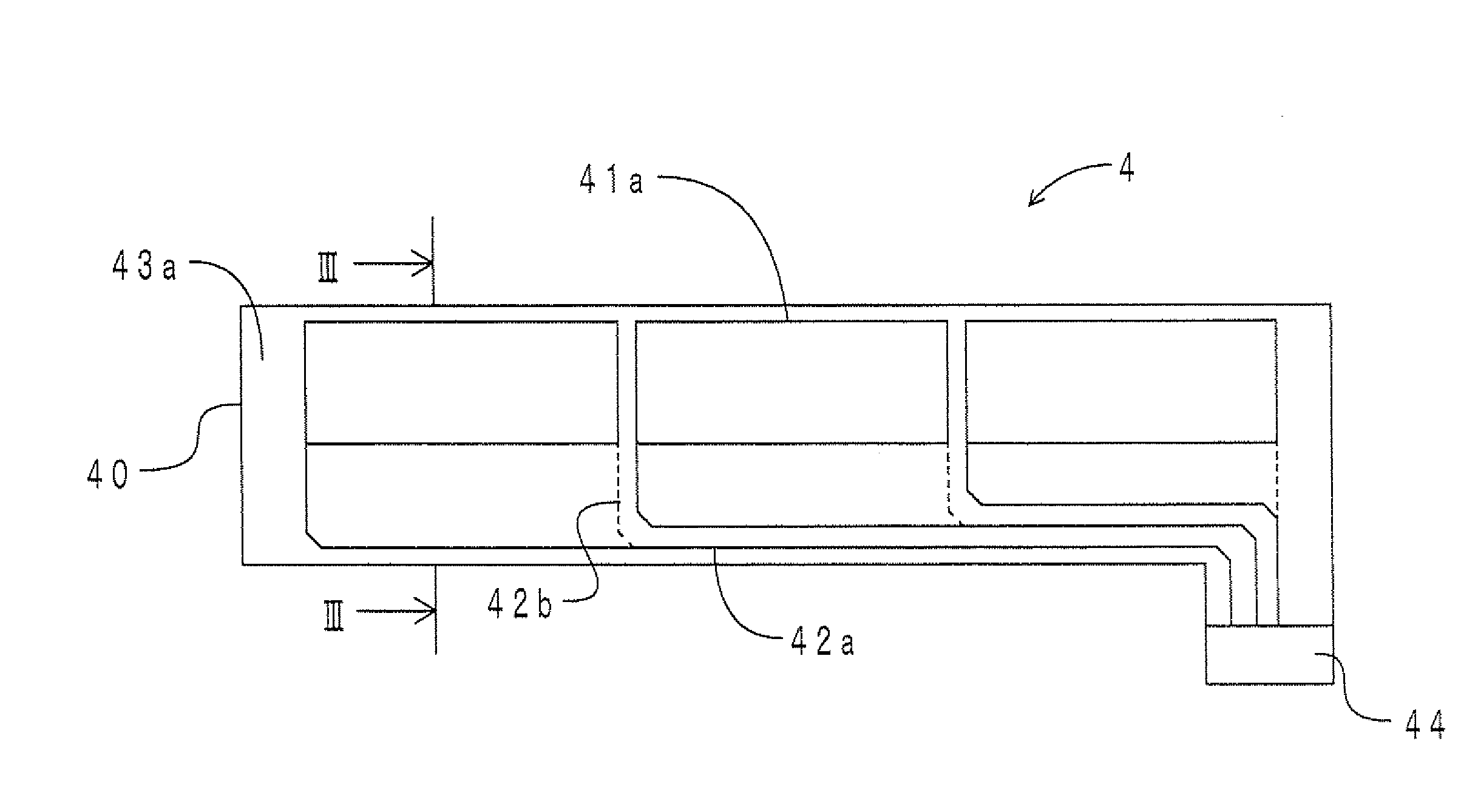
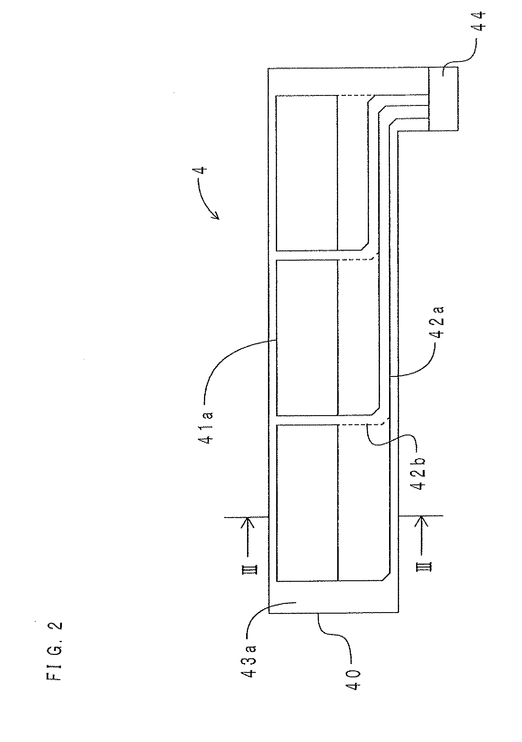
[0107]First, the constitution of the capacitive sensor according to this embodiment will be described. FIG. 2 is a top view of the capacitive sensor. FIG. 3 is a sectional view taken along the line III-III of FIG. 2. As shown in FIGS. 2 and 3, a capacitive sensor 4 includes a dielectric layer 40, a pair of electrodes 41a, 41b, conductors 42a, 42b, and cover films 43a, 43b.

[0108]The dielectric layer 40 is made from urethane rubber and takes a belt shape extending in a left-right direction. The thickness of the dielectric layer 40 is approximately 300 μm.

[0109]The electrode 41a t...

second embodiment

[0117]A capacitive sensor according to this embodiment differs from the capacitive sensor according to the first embodiment by the constitution in which the electrodes and the conductors are formed on the elastic substrate, instead of the dielectric layer. Therefore, only this difference will be hereinafter described.

[0118]FIG. 4 is a top view of the capacitive sensor according to this embodiment. FIG. 5 is a sectional view taken along the line V-V of FIG. 4. Note that, for ease of description, an upper elastic substrate is shown as being transparent in FIG. 4. Further, in FIG. 5, a gap between the upper elastic substrate and a dielectric layer and a gap between a lower elastic substrate and the dielectric layer are emphasized for ease of description.

[0119]As shown in FIGS. 4 and 5, a capacitive sensor 5 includes a dielectric layer 50, a pair of electrodes 51a, 51b, conductors 52a, 52b, an upper elastic substrate 53a, and a lower elastic substrate 53b.

[0120]The upper elastic substr...

third embodiment

[0123][Constitution]

[0124]First, the constitution of a capacitive sensor according to this embodiment will be described. FIG. 6 is a perspective top view of the capacitive sensor according to this embodiment. Note that in FIG. 6, a surface side insulating cover layer and a back side insulating cover layer have been omitted. Further, a back side electrode and a back side conductor are indicated by thin lines, and detection portions are shown as the hatched portions. FIG. 7 is a sectional view taken along the line VII-VII of FIG. 6. Note that in FIG. 7, the thickness of a sensor main body in an up-down direction is emphasized. As shown in FIGS. 6 and 7, a capacitive sensor I according to this embodiment includes a sensor main body 2 and a calculation portion 3.

[0125]The sensor main body 2 includes a dielectric layer 20, surface side electrodes 01X to 16X, back side electrodes 01Y to 16Y, detection portions A0101 to A1616, surface side conductors 01x to 16x, back side conductors 01y to...


PUM


Abstract

A capacitive sensor includes a dielectric layer made of an elastomer and a pair of electrodes arranged via the dielectric layer, and detects deformation on the basis of electrostatic capacity variation between the pair of electrodes. The pair of electrodes contain an elastomer and conductive fillers filled into the elastomer, are expandable and contractible in accordance with deformation of the dielectric layer, and exhibit little conductivity variation even when the pair of electrodes expand and contract. At least one of the dielectric layer and the electrodes is formed by a printing method using a dielectric layer coating containing a formation component of the dielectric layer or an electrode coating containing a formation component of the electrode.

Description

INCORPORATION BY REFERENCE[0001]This application is based on and claims priority under 35 U.S.C. 119 with respect to Japanese Patent Application Nos. 2008-206410 and 2008-206413, both of which were filed on Aug. 8, 2008, and the entire content of which is incorporated herein by reference.BACKGROUND OF THE INVENTION[0002]1. Field of the Invention[0003]The present invention relates to a capacitive sensor that detects deformation and the like on the basis of electrostatic capacity variation between electrodes.[0004]2. Description of the Related Art[0005]With a capacitive sensor, compressive deformation can be detected using variation in electrostatic capacity accompanying variation in the distance between a pair of electrodes. For example, Japanese Patent Application Publication No. JP-05-288619-A and Japanese Patent Application Publication No. JP-2004-117042-A disclose capacitive sensors including a pair of electrodes that face each other via a space. Further, Japanese Patent Applicat...

Claims


Application Information

Patent Timeline
IPC IPC(8): G01R27/26
CPCA61B5/11G01B7/22G01D5/2412G06F2203/04103G01L1/146G01L5/228G06F3/044G01L1/142G06F3/0446G06F3/0445
Inventor HAYAKAWA, TOMONORIKIDA, AYUMUKOBAYASHI, JUNHASHIMOTO, KAZUNOBU
Owner TOKAI RUBBER IND LTD
Why Eureka
Try Eureka