Minimum pulse width for pulse width modulation control

a pulse width modulation and pulse width technology, applied in pulse techniques, dc-dc conversion, power conversion systems, etc., can solve the problems of reducing the voltage of the diode with temperature, limiting the operation of the pwm comparator, and reducing the duty cycl

Active Publication Date: 2010-02-11
INFINEON TECH AMERICAS CORP
View PDF3 Cites 41 Cited by
  • Summary
  • Abstract
  • Description
  • Claims
  • Application Information

AI Technical Summary

Benefits of technology

[0009]Briefly and in general terms, the present invention is directed to a circuit for pulse width modulation comprising a comparator configured to receive a control signal and a ramp signal, the comparator capable of generating a reset signal based on the control signal and the ramp signal. The comparator is preferably an operational amplifier having a supply voltage of about 3.3 volts. The PWM circuit may include a clocking circuit for generating a periodic set signal having a rising set edge and a falling set edge. The periodic set signal may have a pulse width of about 25 percent of the period of the switching frequency. A latching circuit is configured to receive the reset signal and the periodic set signal, wherein the latching circuit generates a pulse width modulated signal based on the reset signal and the periodic set signal. The pulse width modulated signal has a rising PWM edge and a falling PWM edge. The ramp signal is preferably a sawtooth waveform that starts to rise before the falling set edge of the periodic set signal and after the rising set edge of the periodic set signal. The ramp signal may also start to rise before the rising PWM edge of the pulse width modulated signal.

Problems solved by technology

A conventional PWM signal generation circuit, however, may be limited in how small a pulse width, and duty cycle, can be achieved.
As the pulse width decreases, a point is reached where the PWM comparator may not have adequate overdrive to produce a PWM signal below a minimum pulse width.
One drawback of using a diode circuit for this purpose is the fact that the diode voltage decreases with temperature.
Furthermore, diodes may increase noise and noise susceptibility.

Method used


Image

  • Minimum pulse width for pulse width modulation control
  • Minimum pulse width for pulse width modulation control
  • Minimum pulse width for pulse width modulation control

Examples


Embodiment Construction

[0026]In the following description of the preferred embodiment, reference is made to the exemplary drawings for purposes of illustrating specific embodiments of the invention, wherein like reference numerals designate corresponding or like elements among the several views. Embodiments of the invention will be described with respect to voltage mode controllers, and it is to be understood that the invention is not limited to the specific embodiments described and illustrated herein.

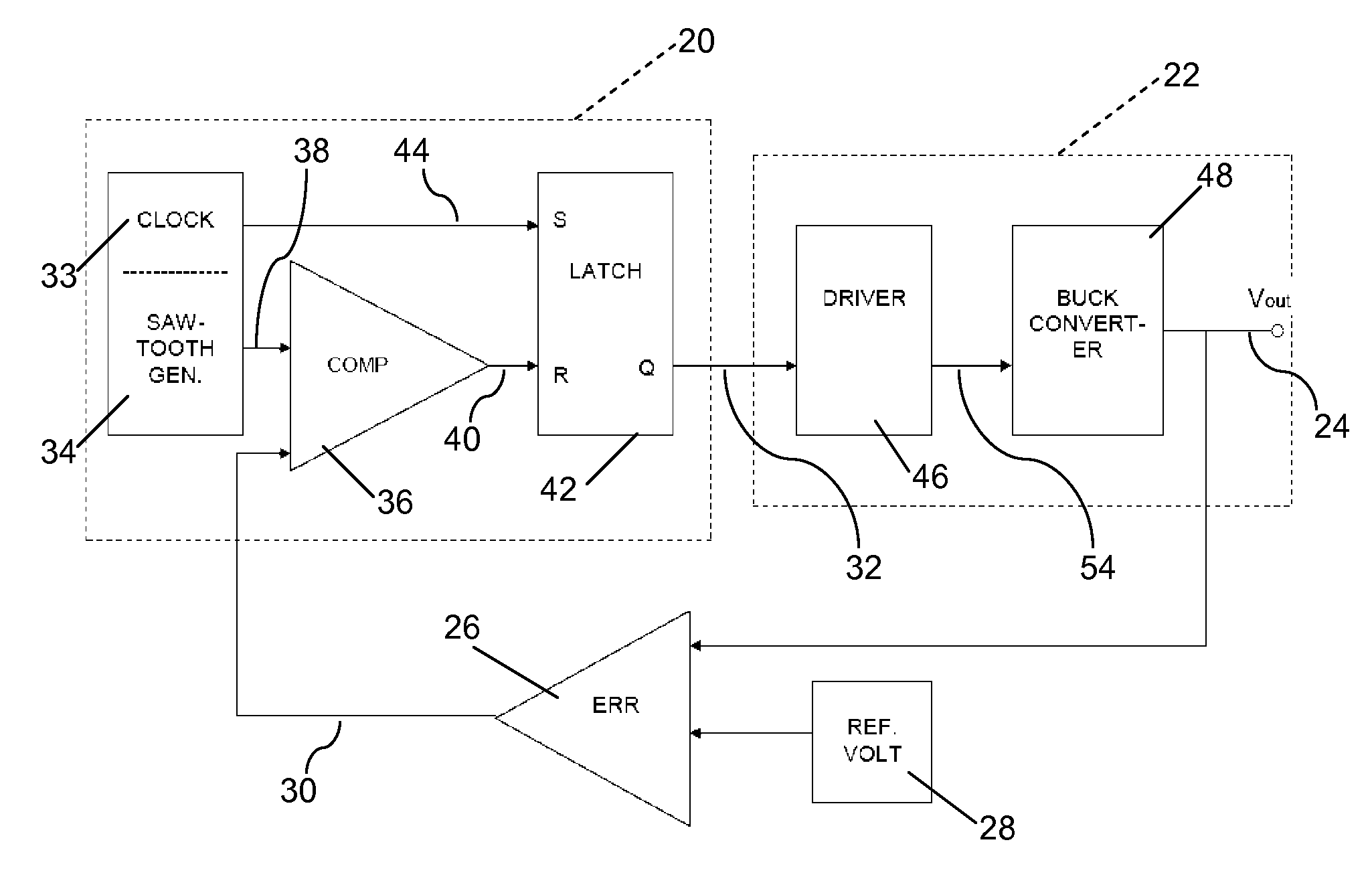
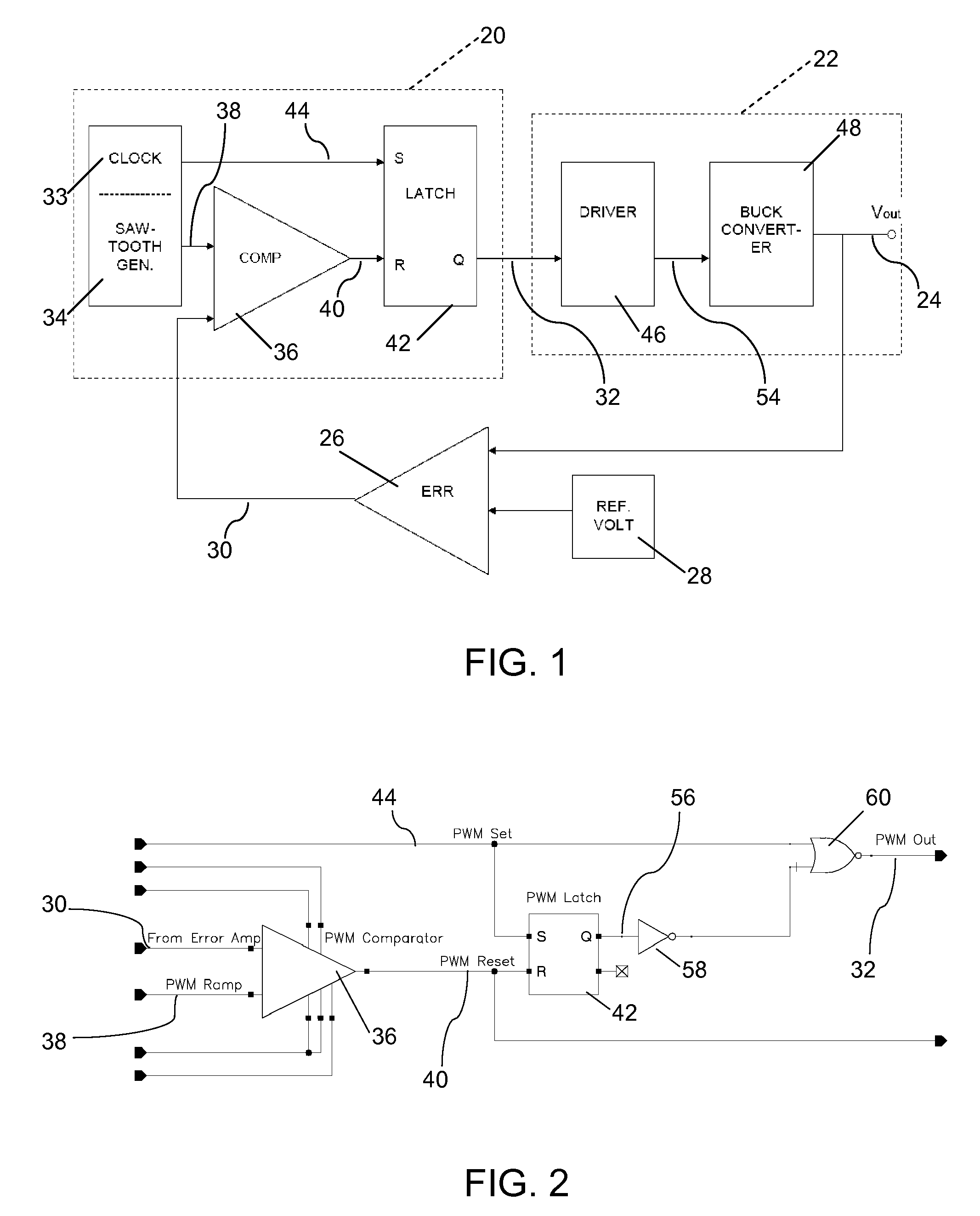
[0027]FIG. 1 illustrates a block diagram of a pulse width modulation (PWM) circuit 20. The PWM circuit 20 controls a power converter 22, the voltage output 24 or Vout of which is compared to a voltage reference 28 by a feedback voltage error comparator 26. The feedback signal 30 resulting from this comparison is supplied to the PWM circuit 20 for use as a feedback error control in adjusting the control pulse 32 provided to the driver circuit 46 of the power converter 22. The feedback signal may also be refe...


PUM


Abstract

The rising edge of a pulse width modulated output signal occurs after an input ramp signal starts to rise. The ramp signal starts to rise after the rising edge of a periodic set signal and before the falling edge of a periodic set signal. A feedback control signal intersects a substantially linear region of the ramp signal to generate a reset signal using a PWM comparator. The periodic set signal and reset signal are input to a latching circuit to generate the pulse width modulated output signal. The minimum pulse width can approach zero while having adequate overdrive to the PWM comparator. Having the rising edge of the reset signal rise before the falling edge of the set signal can allow a zero percent duty cycle without the need for a ramp offset voltage.

Description

[0001]The present invention relates in general to pulse width modulation (“PWM”) and, more particularly, to improved minimum pulse widths for a voltage mode controller.BACKGROUND[0002]Pulse width modulation (“PWM”) is a common circuit technique where the width of a pulse in a periodic signal is varied or “modulated” to an extent that depends on the signal needed to control a connected device. PWM is often used to control the supply of electrical power to a device and may be used as a voltage mode controller in power control systems. Using PWM, which switches the power on and off very rapidly, a DC voltage may be efficiently and accurately converted to a lower DC voltage. Through continually adjusting the pulse width, as necessary, the lower DC voltage level can be maintained.[0003]As an example, the pulse from the PWM circuit may be used to control the switch in a DC to DC converter circuit, such as a buck converter in a closed loop voltage mode control system. The width of the PWM ...

Claims


Application Information

Patent Timeline
Patent Type & Authority Applications(United States)
IPC IPC(8): H03K7/08
CPCH03K7/08H02M3/156
Inventor STEVENSON, BRIANPARTO, PARVIZCHEN, YANG
Owner INFINEON TECH AMERICAS CORP
Why Eureka
Try Eureka