
Radio frequency identification (RFID) surveillance tag

a radio frequency identification and surveillance tag technology, applied in the direction of instruments, electric signalling details, burglar alarm mechanical actuation, etc., can solve the problems of labor-intensive operations and often less-than-effective data management, and achieve the effect of reducing the likelihood of unintentional bumping and impact during handling

Active Publication Date: 2010-02-11
UCHICAGO ARGONNE LLC
View PDF9 Cites 47 Cited by
  • Summary
  • Abstract
  • Description
  • Claims
  • Application Information

AI Technical Summary

Benefits of technology

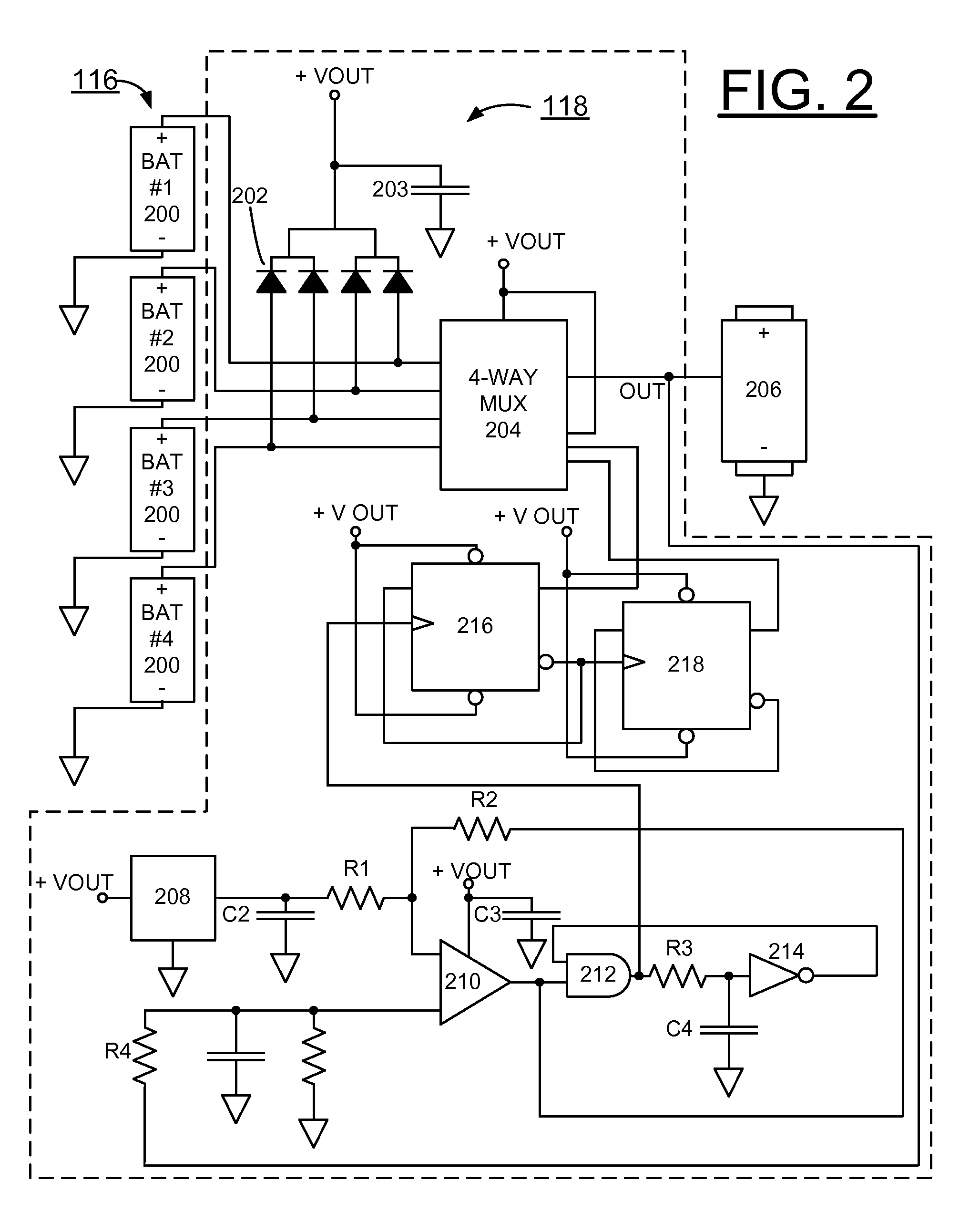
[0013]In accordance with features of the invention, a low battery status sensor triggers a warning responsive to a low-battery state for the operator to take action. The tag memory is nonvolatile so that a low-battery state will not result in a loss of data.
[0014]In accordance with features of the invention, the back plate includes a predefined shape selectively provided for mounting with the associated packaging, and the tag body includes a universal form for use with multiple different types of the associated packaging. The selected configuration of the back plate enables simple modifications to provide different configurations and packagings. To reduce the likelihood of unintentional bumping and impact during handling of drums, the RFID surveillance tag has a slim profile that fits within the footprint of a drum cover of the associated packaging.

Problems solved by technology

Management of multiple, such as thousands of packagings of radioactive and fissile materials, in storage, transportation and disposal is a serious challenge for United States Department of Energy (DOE) to ensure accountability, safety, security, worker and public health, and protection of the environment.
Many know arrangements for inventory and quality control typically utilize paper and file systems, resulting in labor-intensive operations and often less-than-effective data management.

Method used


Image

  • Radio frequency identification (RFID) surveillance tag
  • Radio frequency identification (RFID) surveillance tag
  • Radio frequency identification (RFID) surveillance tag

Examples


Embodiment Construction

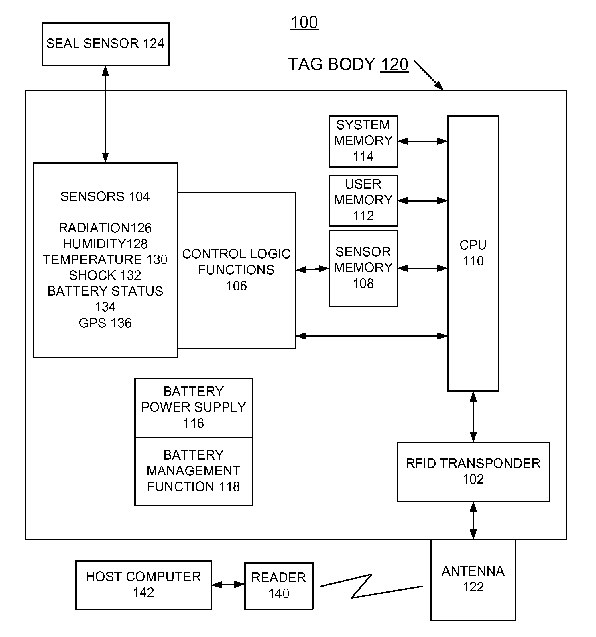
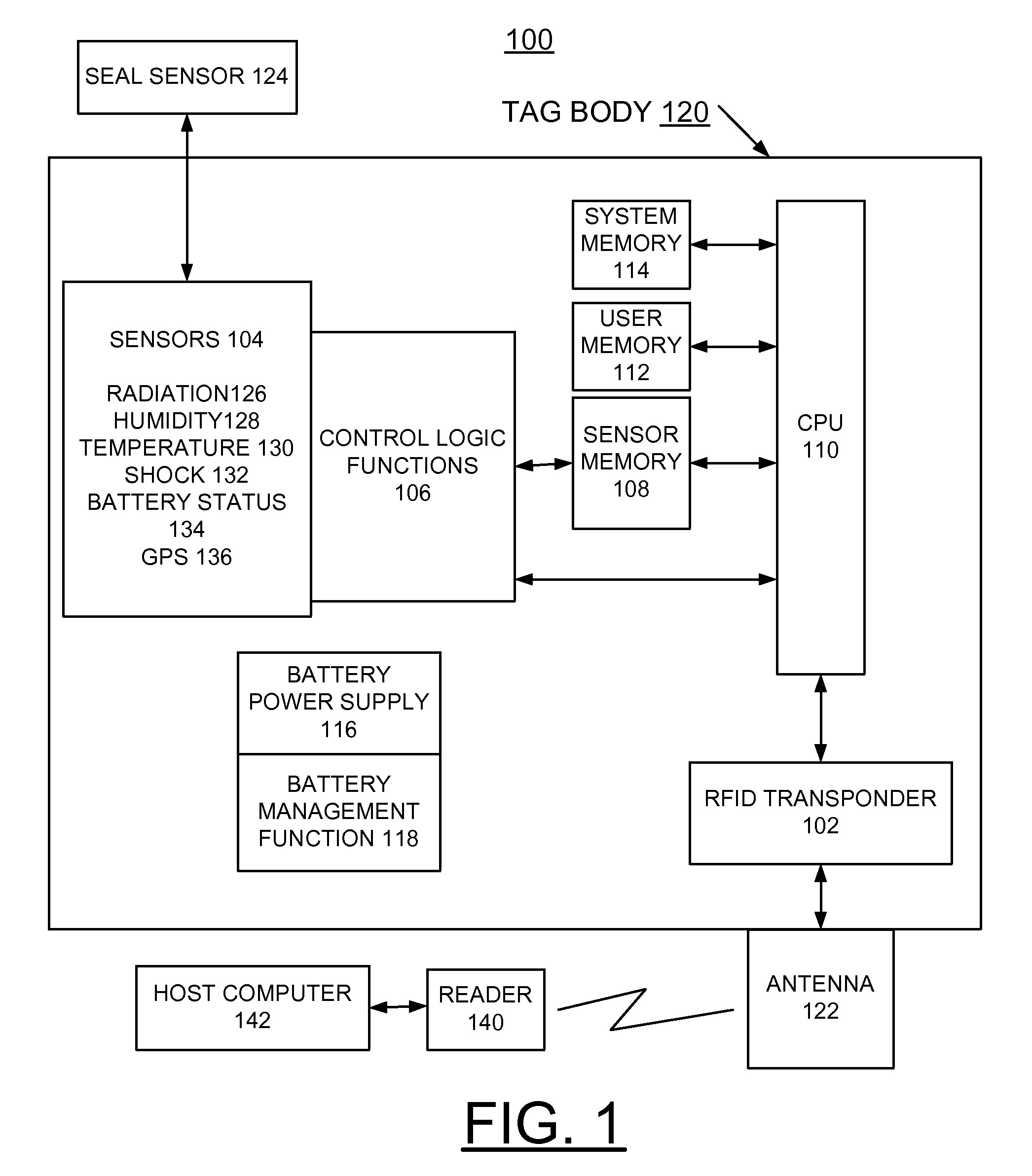
[0024]In accordance with features of the invention, a radio frequency identification (RFID) surveillance tag is provided to supplement existing safeguard measures and provide real-time alarm when preset thresholds are exceeded. Active RFID surveillance tags of the invention are distinct from passive RFID tags as they are equipped with an onboard power supply as well as sensors for monitoring environmental conditions and other critical parameters, such as the status of seals and object movement.

[0025]Advantages of the application of active RFID surveillance tags of the invention in nuclear materials management are enhanced safety and security, reduced need for manned surveillance, real-time access of status and history data, and overall cost-effectiveness. The RFID surveillance tags of the invention are adapted to provide adequate resistance to radiation and battery life under service conditions that include storage and transportation of radioactive materials containers.

[0026]Having ...


PUM


Abstract

An enhanced method and apparatus are provided for tracking and managing a plurality of packagings, particularly packagings containing radioactive and fissile materials. A radio frequency identification (RFID) surveillance tag is provided with an associated packaging. The RFID surveillance tag includes a tag body and a back plate including predefined mounting features for mounting the surveillance tag to the associated packaging. The RFID surveillance tag includes a battery power supply. The RFID surveillance tag includes a plurality of sensors monitoring the associated packaging including a seal sensor. The seal sensor includes a force sensitive material providing a resistivity change responsive to change in a seal integrity change of the associated packaging. The resistivity change causes a seal integrity tag alarm. A tag memory stores data responsive to tag alarms generated by each of the plurality of sensors monitoring the associated packaging.

Description

[0001]This application claims the benefit of U.S. Provisional Application No. 61 / 086,698 filed on Aug. 6, 2008.CONTRACTUAL ORIGIN OF THE INVENTION[0002]The United States Government has rights in this invention pursuant to Contract No. W-31-109-ENG-38 between the United States Government and The University of Chicago and / or pursuant to Contract No. DE-AC02-06CH11357 between the United States Government and UChicago Argonne, LLC representing Argonne National Laboratory.FIELD OF THE INVENTION [0003]The present invention relates to an improved method and apparatus for tracking and managing a plurality of packagings, particularly packagings containing radioactive and fissile materials.DESCRIPTION OF THE RELATED ART [0004]Management of multiple, such as thousands of packagings of radioactive and fissile materials, in storage, transportation and disposal is a serious challenge for United States Department of Energy (DOE) to ensure accountability, safety, security, worker and public health,...

Claims


Application Information

Patent Timeline
Patent Type & Authority Applications(United States)
IPC IPC(8): G08B1/08G06K7/01G06K19/00
CPCG06K19/0717G08B13/1436G06K19/07749G06K19/0723G08B13/149
Inventor TSAI, HAN-CHUNGLIU, YUNG Y.
Owner UCHICAGO ARGONNE LLC
Learn More