Photoacoustic point spectroscopy

a technology of photoacoustic point and spectroscopy, which is applied in the direction of spectrometry/spectrophotometry/monochromators, instruments, optical radiation measurement, etc., can solve the problems of difficult detection of pressure/sound waves, local heating and pressure/sound waves, and reduce the range and sensitivity of producing a photoacoustic spectrum

Inactive Publication Date: 2010-02-11
UT BATTELLE LLC +1
View PDF43 Cites 9 Cited by
  • Summary
  • Abstract
  • Description
  • Claims
  • Application Information

AI Technical Summary

Benefits of technology

[0032]One or more embodiments of the disclosure may be referred to herein, individually and/or collectively, by the term “invention” merely for convenience and without intending to voluntarily limit the scope of this application to any particular invention or inventive concept. Moreover, although specific embodiments have been illustrated and described herein, it should be appreciated that any subseq

Problems solved by technology

The absorption may result in local heating and a pressure/sound wave.
In an open environment, it may be difficult to detect these waves.
The waves may spread and stretch their energy outward and they may be

Method used


Image

  • Photoacoustic point spectroscopy
  • Photoacoustic point spectroscopy
  • Photoacoustic point spectroscopy

Examples


Embodiment Construction

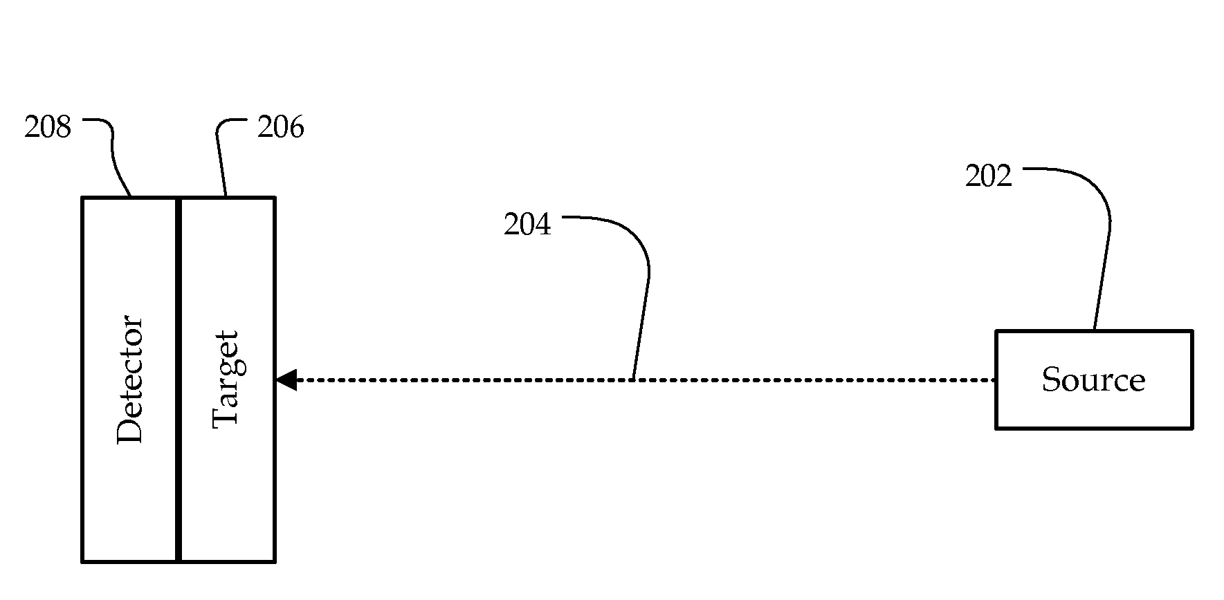
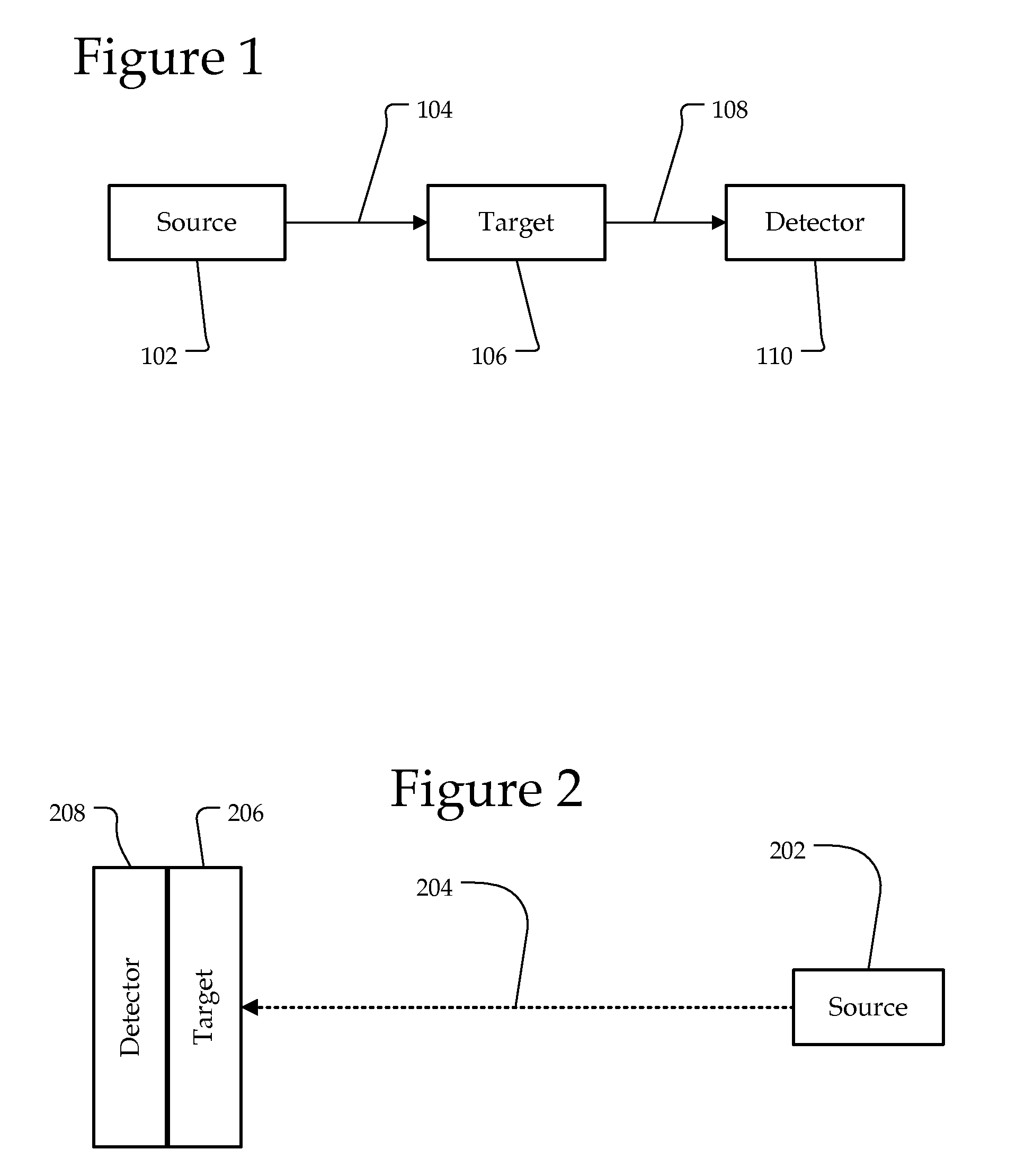
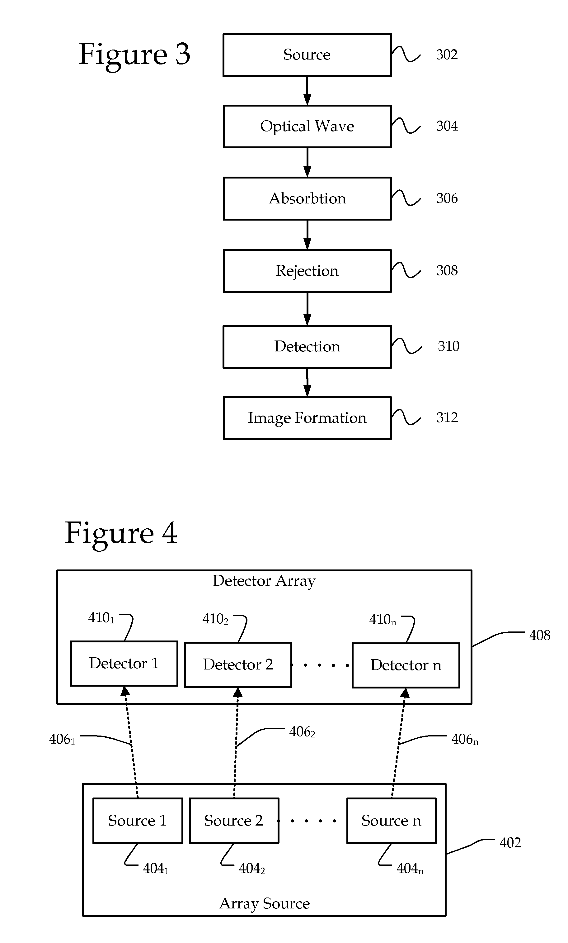
[0011]By way of introduction, a system and method for generating a photoacoustic spectrum without an enclosed chamber is described. A source may emit a beam to a target and a detector measures signals generated as a result of the beam being emitted on the detector. The detector is coated with a target material, residue, or molecule. By emitting a chopped / pulsed light beam to the target coating on the detector, it may be possible to determine the target's optical absorbance by monitoring the intensity of photoacoustic vibration produced by the light on the detector at different wavelengths. As the wavelength of light is changed, the target may absorb or reject each optical frequency. Rejection may decrease the photoacoustic intensity at the detector and absorption may increase the intensity. Accordingly, an identifying spectrum of the target coating may be made with the photoacoustic wave intensity variation of the detector as a function of illuminating wavelength. The detector may c...


PUM


Abstract

A system and method are disclosed for generating a photoacoustic spectrum in an open or closed environment with reduced noise. A source may emit a beam to a target substance coated on a detector that measures acoustic waves generated as a result of a light beam being absorbed by the target substance. By emitting a chopped/pulsed light beam to the target substance on the detector, it may be possible to determine the target's optical absorbance as the wavelength of light is changed. Rejection may decrease the intensity of the acoustic waves on the detector while absorption may increase the intensity. Accordingly, an identifying spectrum of the target may be made with the intensity variation of the detector as a function of illuminating wavelength.

Description

RELATED APPLICATION[0001]This application is related to the application entitled “REVERSE PHOTOACOUSTIC STANDOFF SPECTROSCOPY,” (Atty. Dkt. 13489 / 28, 2138) filed on Aug. 11, 2008, U.S. Ser. No. ______, now U.S. Pat. No. ______, which is incorporated by reference.STATEMENT REGARDING FEDERALLY SPONSORED RESEARCH[0002]This invention was made with government support under Contract No. DE-AC05-00OR22725 awarded by the U.S. Department of Energy. The government has certain rights in the invention.BACKGROUND[0003]Photoacoustic spectroscopy (PAS) may utilize the photoacoustic effect. The photoacoustic effect may include a conversion between light and acoustic waves due to absorption and localized thermal excitation. Light may be absorbed and transformed into kinetic energy. The absorption may result in local heating and a pressure / sound wave. A measurement of the sound waves at different wavelengths may be used to generate a photoacoustic spectrum of a sample. In an open environment, it may ...

Claims


Application Information

Patent Timeline
IPC IPC(8): G01N21/00
CPCG01N29/2418G01N21/1702
Inventor VAN NESTE, CHARLES W.SENESAC, LAWRENCE R.THUNDAT, THOMAS G.
Owner UT BATTELLE LLC
Why Eureka
Try Eureka