

Backlight Module and Light Emitting Diode Module Thereof
- Summary
- Abstract
- Description
- Claims
- Application Information
AI Technical Summary
Benefits of technology
Problems solved by technology
Method used
Image

Examples
Embodiment Construction
[0024]Reference will now be made in detail to the present embodiments of the invention, examples of which are illustrated in the accompanying drawings. Wherever possible, the same reference numbers are used in the drawings and the description to refer to the same or like parts.
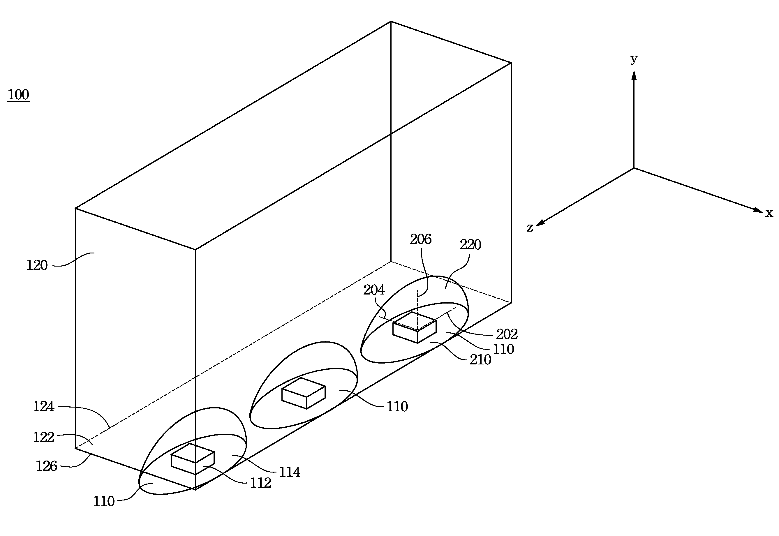
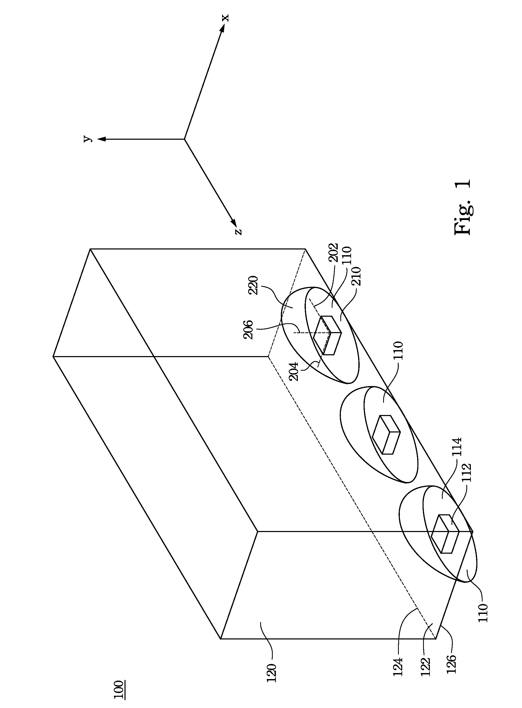
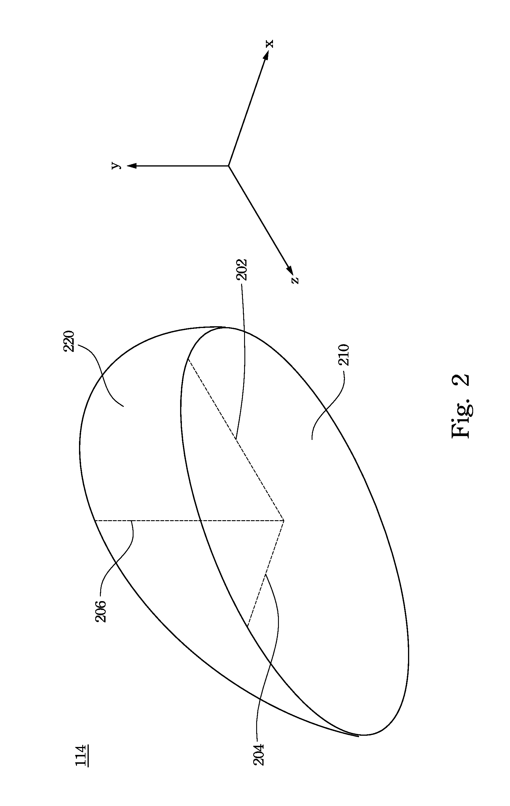
[0025]Please refer to FIG. 1. FIG. 1 is a three-dimensional diagram of a backlight module 100 according to an embodiment of this invention. The backlight module 100 supplies light to the liquid crystal display (referred to as LCD). In the embodiment of this invention, the backlight module 100 at least contains light emitting diode modules (refer to as LED modules) 110 and a light guide plate 120. The light guide plate 120 may guide light emitted from the LED modules 110 to a panel (not shown) of the LCD. The LED module 110 includes a light emitting diode die 112 and a package structure 114, wherein the die 112 is embedded in the package structure 114. The package structure 114 may spread light emitted from the...
PUM
 Abstract
Description
Claims
Application Information