Electrophoretic mobility measuring apparatus

a technology of mobility measuring apparatus and electric field, which is applied in the direction of fluid pressure measurement, liquid/fluent solid measurement, peptide measurement, etc., can solve the problems of difficult to measure the velocity of particles moving in the electric field direction, deteriorating measurement precision, and reducing optical attenuation, so as to achieve excellent sensitivity and reduce optical attenuation

Active Publication Date: 2008-11-11
OTSUKA DENSHI CO LTD +1
View PDF16 Cites 9 Cited by
  • Summary
  • Abstract
  • Description
  • Claims
  • Application Information

AI Technical Summary

Benefits of technology

[0026]According to the present invention having the arrangement above-mentioned, light is incident upon the inside of the cell through the transparent electrode, and the outgoing light which scatters from the sample at a predetermined angle θ with respect to the incident angle, is received through the transparent electrode. Further, the direction of the scattering vector which is the difference between the incident vector of the incident light and the outgoing vector of the scattering light, is set substantially identical with the direction of the normal line of the transparent electrode face. It is therefore possible to measure the velocity of the particles, along the direction of the normal line of the transparent electrode or the direction of the electric field, located in the vicinity of the transparent electrode face which is not so inwardly remote from the transparent electrode face in the cell. This enables measurement of particle moving speed with excellent sensitivity with optical attenuation reduced. Further, an opaque electrode having an incident window and an outgoing window may be used instead of the transparent electrode.

Problems solved by technology

In other words, for a concentrated sample which causes the incident light to be greatly attenuated, the measuring precision has remarkably been deteriorated or the measurement itself could not be made.
This makes it difficult to measure the velocity of the particles which move in the electric field direction.

Method used


Image

  • Electrophoretic mobility measuring apparatus
  • Electrophoretic mobility measuring apparatus
  • Electrophoretic mobility measuring apparatus

Examples


examples

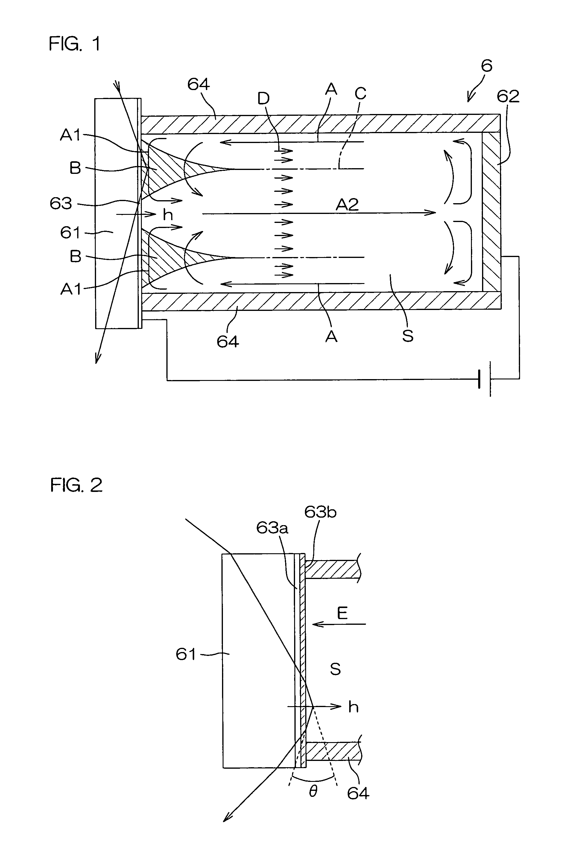
[0064]As shown in FIG. 12, an ITO film 63a having a width of 10 mm, a thickness of 100 nm and a length of 6 mm was formed on a quartz glass 61, and then coated with a platinum 63b having a thickness of about 4 nm. The light transmission in the vertical direction was measured as about 50%. The electric resistance value between the end faces was calculated. That is, the ITO's resistance value was 8.4Ω since the ITO's electric resistivity was 1.4×10⁻⁴Ωcm and the end-face section area was 10−5 cm2. The platinum's electric resistivity is 10×10−6Ωcm. However, the electric resistivity of platinum in the form of a thin film, seems to be a half of the value above-mentioned. Since the end-face section area was 4×10⁻⁷ cm2, the platinum's electric resistivity was 38.25Ω. The combined resistance was equal to 1 / (1 / 8.4+1 / 38.25)=6.9Ω. Accordingly, since the platinum film is thin even though the platinum's electric resistivity itself is low, the use of platinum does not contribute so much to reducti...


PUM

PropertyMeasurementUnit
wavelengthaaaaaaaaaa
refractive indexaaaaaaaaaa

Abstract

The present invention provides an electrophoretic mobility measuring apparatus capable of conducting measurement with high sensitivity with optical attenuation reduced by incidence of light through the electrode face. This apparatus comprises a transparent electrode 63 forming a part of a cell wall of a cell 6 capable of confining a sample, and the other electrode 62 opposite to the transparent electrode 63. A voltage is applied across these electrodes 62, 63, and light is incident upon the inside of the cell 6 through the transparent electrode 63. The scattering light which scatters from a sample S at a predetermined angle θ with respect to the incident angle, is received through the transparent electrode 63. The Doppler displacement is then measured based on the difference in frequency between the incident light and the outgoing light. The direction of the scattering vector which is the vector difference between incident and outgoing vectors, is substantially identical with that of the normal line h of the transparent electrode face.

Description

[0001]The disclosure of Japanese Patent Application No. 2003-47824, filed on Feb. 25, 2003, and Japanese Patent Application No. 2003-85678, filed on Mar. 26, 2003, is incorporated herein by reference.FIELD OF THE INVENTION[0002]The present invention relates to an electrophoretic mobility measuring apparatus capable of measuring the electrophoretic speed of particles in a solution.DESCRIPTION OF RELATED ART[0003]Polymers or their aggregates, i.e., colloid particles are electrically charged in a water solution by adsorption of dissociation groups or ions. The potential formed by such charging is called a zeta (ζ) potential. To measure the charge amount of particles, it has been practiced to apply an electric field to the particles for measuring the moving speed (electrophoretic mobility) thereof.[0004]FIG. 13 is a schematic section view of a conventional electrophoretic mobility measuring apparatus. The electrophoretic mobility measuring apparatus has a rectangular parallelepiped or c...

Claims


Application Information

Patent Timeline
Patent Type & Authority Patents(United States)
IPC IPC(8): G01N27/453G01N27/26G01N15/00G01N27/447G01S17/58
CPCG01N15/00G01N27/447G01S17/58G01N27/44721G01N2015/0003G01N2015/1075
Inventor SEKIWA, MITSUNAOTSUTSUI, KAZUNORIMORISAWA, KATSUHIROFUJIMOTO, TAKASHITOYOSHIMA, ATSUSHI
Owner OTSUKA DENSHI CO LTD
Why Eureka
Try Eureka