Electric fuel pump capable of supplying fuel at high flow rate

a fuel pump and electric technology, applied in the direction of positive displacement liquid engines, pumping machines, machines/engines, etc., can solve the problems of lowering the efficiency of the motor portion 103/b>, the inability to meet the requirement of supplying fuel to the engine, and the inability to supply fuel to the engine at a high flow rate, etc., to achieve the effect of reducing the gap, high flow rate of the electric fuel pump, and reducing the magnetic resistance between the rotor

Active Publication Date: 2010-02-11
AISAN IND CO LTD
View PDF23 Cites 48 Cited by
  • Summary
  • Abstract
  • Description
  • Claims
  • Application Information

AI Technical Summary

Benefits of technology

[0018]Moreover, with the fuel passage, it is also possible to reduce a gap between the outer periphery of the rotor and the inner periphery of the stator of the motor portion while ensuring a sufficiently high flow rate of the electric fuel pump. Further, with the reduced gap, the magnetic reluctance between the rotor and stator of the motor portion can be reduced and the magnetic attraction between the same can be increased. As a result, the efficiency of the motor portion can be improved.
[0019]Accordingly, the electric fuel pump according to the present invention can supply fuel at a high flow rate without lowering the efficiency of the motor portion.

Problems solved by technology

However, with the above-described electric fuel pump, it is difficult to meet the requirement of supplying fuel to the engine at a high flow rate when the engine is used in a recent four-wheel motor vehicle.
As a result, the efficiency of the motor portion 103 is lowered, making it impossible to supply the fuel to the engine at a high flow rate.
However, for the improved electric fuel pump, there is still a limitation in supplying fuel to the engine at a high flow rate.
This is because the clearances, which make up the second fuel passage, are provided between the radially inner ends of the teeth of the stator core, and there is accordingly a limitation in setting the clearances large.

Method used


Image

  • Electric fuel pump capable of supplying fuel at high flow rate
  • Electric fuel pump capable of supplying fuel at high flow rate
  • Electric fuel pump capable of supplying fuel at high flow rate

Examples


first embodiment

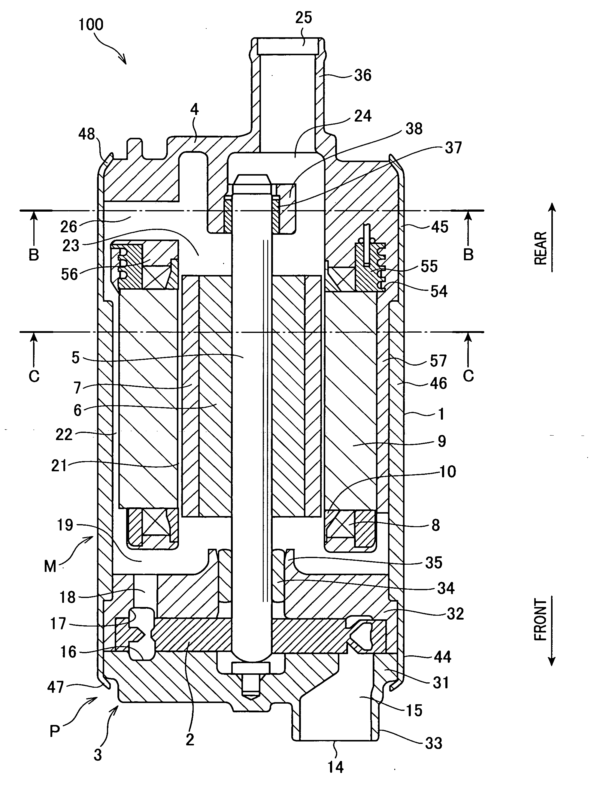
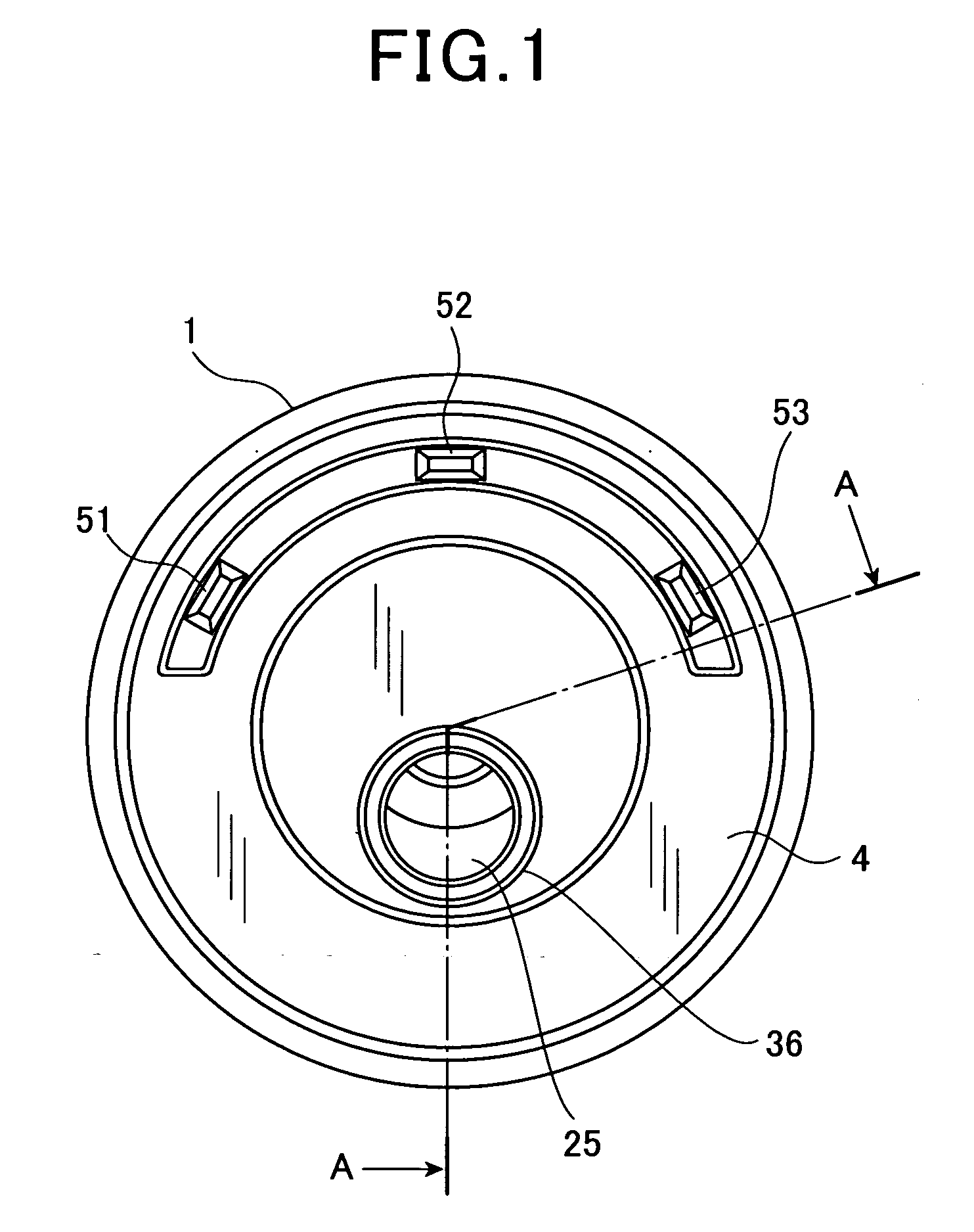
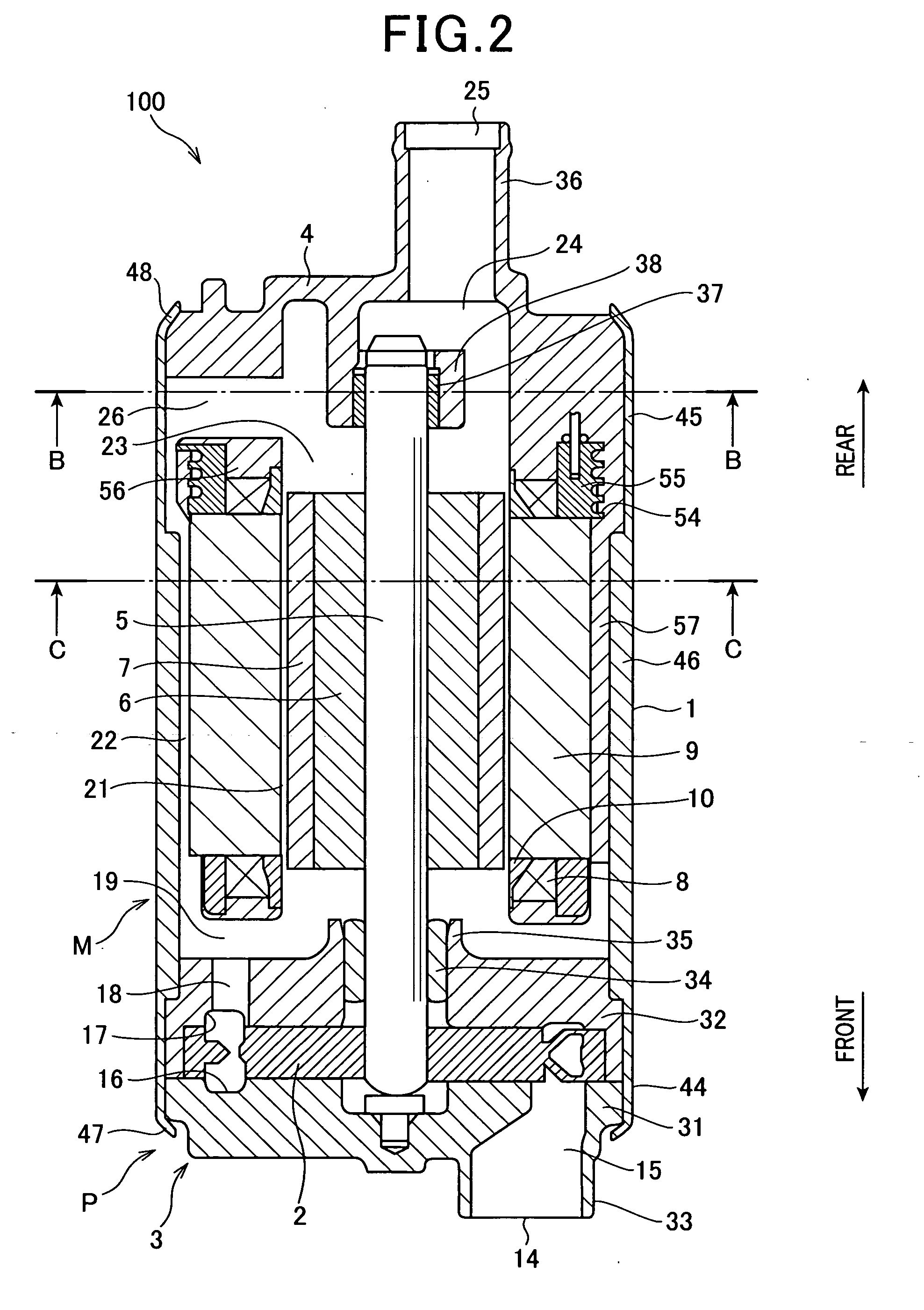
[0038]FIGS. 1-4 show an electric fuel pump 100 according to the first embodiment of the invention.

[0039]In the present embodiment, the electric fuel pump 100 is used in a fuel supply system for an internal combustion engine of, for example, a four-wheel motor vehicle. The fuel supply system includes, in addition to the electric fuel pump 100, a fuel tank (not shown), a fuel delivery pipe (not shown), and a plurality of fuel injectors (not shown). The fuel tank stores fuel, such as gasoline. The electric fuel pump 100 sucks fuel from the fuel tank and pressurizes it. The fuel delivery pipe temporarily stores the fuel pressurized by the electric fuel pump 100. Each of the fuel injectors injects the fuel stored in the fuel delivery pipe into a corresponding one of a plurality of cylinders of the engine at an optimal timing in an intake stroke.

[0040]In addition, the fuel delivery pipe is located in an engine compartment of the vehicle. Each of the fuel injectors is mounted on either a c...

second embodiment

[0101]FIG. 6 shows the motor portion M according to the second embodiment of the invention. This motor portion M has almost the same configuration as the motor portion M according to the first embodiment; therefore, only the differences therebetween will be described hereinafter.

[0102]As described previously, in the first embodiment, the motor portion M includes the stator core that is composed of the plurality of stator core pieces 11.

[0103]In comparison, in the present embodiment, as shown in FIG. 6, the motor portion M includes a stator core 70 that is formed in one piece and continuously extends to enclose the entire radially outer periphery of the magnet 7 of the rotor.

[0104]More specifically, the stator core 70 includes a yoke portion 71 and a plurality of tooth portions 72. The yoke portion 71 has the shape of a polygonal tube and faces the radially inner periphery of the housing 1 through the second fuel passage 22. Each of the tooth portions 72 protrudes radially inward fro...

third embodiment

[0112]FIG. 7 shows the motor portion M according to the third embodiment of the invention. This motor portion M has almost the same configuration as the motor portion M according to the second embodiment; therefore, only the differences therebetween will be described hereinafter.

[0113]As described previously, in the second embodiment, the motor portion M includes the resin members 57 and 58 by which the second fuel passage 22 is divided into the plurality of sections and the stator core 7 is fixed to the housing 1.

[0114]In comparison, in the present embodiment, as shown in FIG. 7, the resin members 57 and 58 are omitted from the motor portion M. Instead, the stator core 70 further has a plurality of (e.g., six in the present embodiment) protrusions 84 for performing the functions of the resin members 57 and 58.

[0115]More specifically, each of the protrusions 84 protrudes radially outward from a corresponding one of the apical parts 81 of the yoke portion 71 of the stator core 70 and...


PUM


Abstract

An electric fuel pump is disclosed which includes a pump portion, a motor portion, a housing, and a fuel passage. The pump portion pressurizes fuel. The motor portion drives the pump portion. The motor portion includes a rotor with a rotating shaft and a stator that surrounds an outer periphery of the rotor. The housing surrounds, at least, an outer periphery of the stator of the motor portion. The fuel passage, through which the fuel pressurized by the pump portion passes the motor portion, is made up of a clearance between the outer periphery of the stator of the motor portion and an inner periphery of the housing. The clearance extends, at least, in the axial direction of the rotating shaft of the rotor of the motor portion.

Description

CROSS-REFERENCE TO RELATED APPLICATION[0001]This application is based on and claims priority from Japanese Patent Applications No. 2008-202608, filed on Aug. 6, 2008, and No. 2009-28749, filed on Feb. 10, 2009, the contents of which are hereby incorporated by reference into this application.BACKGROUND OF THE INVENTION[0002]1. Technical Field of the Invention[0003]The present invention relates generally to electric fuel pumps that include a pump portion and a motor portion. More particularly, the invention relates to an electric fuel pump that has an improved structure by which the pump can supply fuel at a high flow rate.[0004]2. Description of the Related Art[0005]There is known, for example from Japanese Patent First Publication No. 2005-110477, an electric fuel pump for an internal combustion engine which includes a pump portion and a motor portion. The pump portion sucks fuel from a fuel tank into pump chambers, pressurizes the sucked fuel in the pump chambers, and discharges th...

Claims


Application Information

Patent Timeline
Patent Type & Authority Applications(United States)
IPC IPC(8): F04B35/04H02K9/19
CPCF02M37/08H02K1/185H02K7/14H02K5/20H02K5/12
Inventor OOTA, YUICHIROUOOTAKE, MASAYANAGATA, KIYOSHI
Owner AISAN IND CO LTD
Why Eureka
Try Eureka