Analysis unit intended to be used in analysis apparatus

a technology of analysis apparatus and analysis unit, which is applied in the field of analysis unit, can solve the problems of high cost of manufacturing receptacles and therefore cartridges, risk of leakage of receptacles, and inability to produce half-shells, so as to improve stirring of magnetic particles and reduce manufacturing costs

Active Publication Date: 2010-02-11
IMMUNODIAGNOSTIC SYST FRANCE
View PDF12 Cites 18 Cited by
  • Summary
  • Abstract
  • Description
  • Claims
  • Application Information

AI Technical Summary

Benefits of technology

[0042]Moreover, in contrast to that described in the documents EP 1,432,516 and EP 0,871,894, the means for rotationally driving the container are not provided directly on the container which is disposable, but on the tubular support. This minimizes the cost of manufacture of the container and therefore of the analysis unit.
[0043]Preferably, the inner wall of the container has longitudinal fins. This helps improve stirring of the magnetic particles when the container is rotationally driven.

Problems solved by technology

Since injection-molding and ultrasound-welding require very costly tools, the cost of manufacturing the receptacles and therefore the cartridge is very high.
Thus, it is not possible to produce these half-shells using another less costly molding technique.
Moreover, the assembly of a large number of parts may result in the risk of leakages of the receptacles and therefore discarding of a certain number of receptacles.
Moreover, in order to identify these possible leakage defects in the receptacles, it is required to provide very costly means on the vessel production line.
As a result the manufacture and assembly of a cartridge such as that described in the document EP 0,871,894 is very complex and costly.
Thus, as before, the cost of manufacturing these cartridges is very high since the receptacles are obtained by means of injection-molding of a large number of parts and ultrasound-welding of these parts.
Thus, it is not possible to produce these half-shells using another less costly molding technique.
As a result, the manufacture of an analysis unit such as that described in the document EP 1,432,516 is very complex and costly.

Method used


Image

  • Analysis unit intended to be used in analysis apparatus
  • Analysis unit intended to be used in analysis apparatus
  • Analysis unit intended to be used in analysis apparatus

Examples


Embodiment Construction

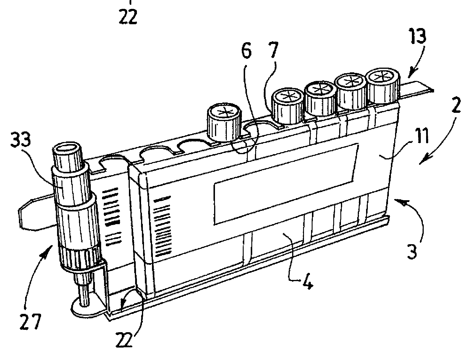
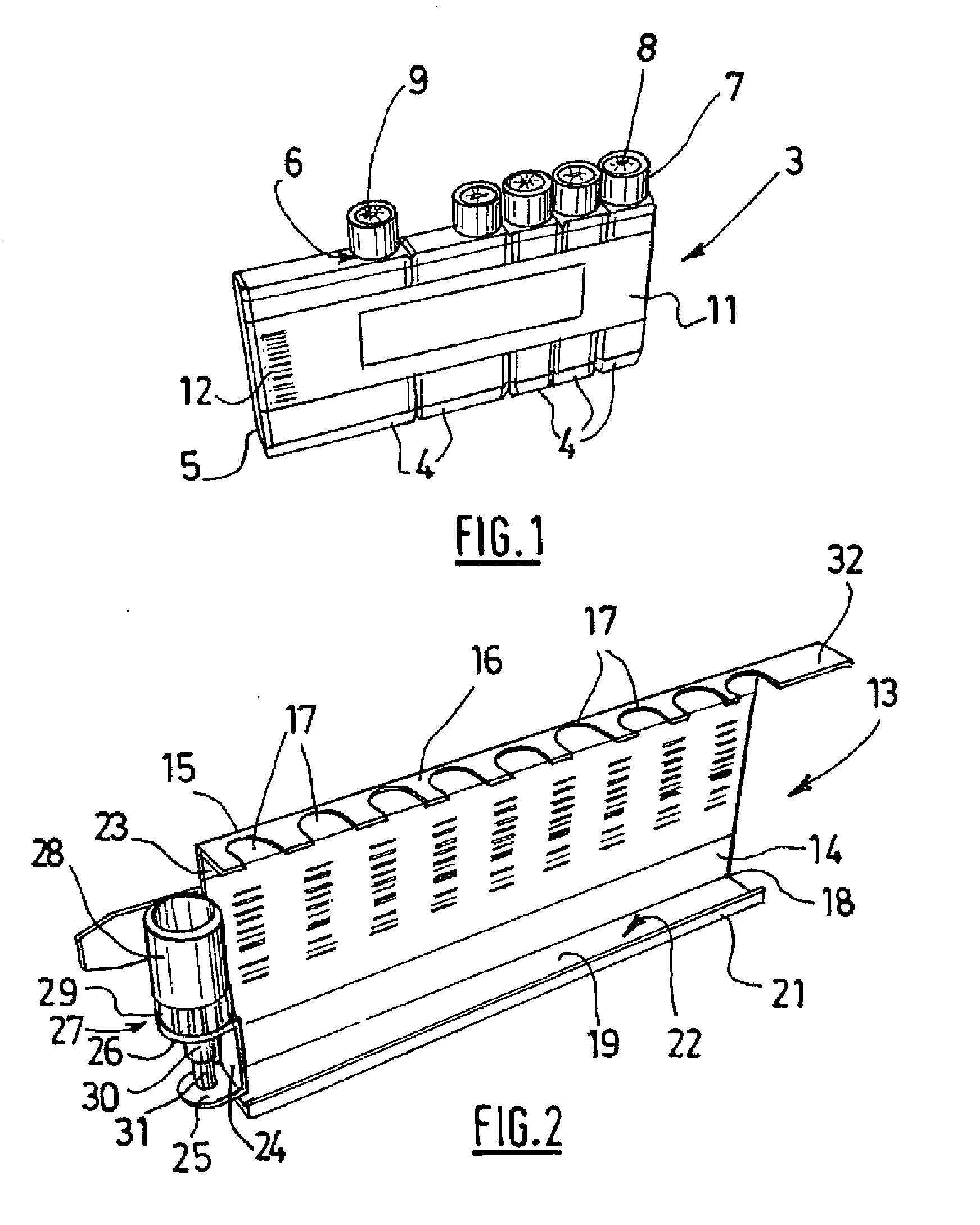
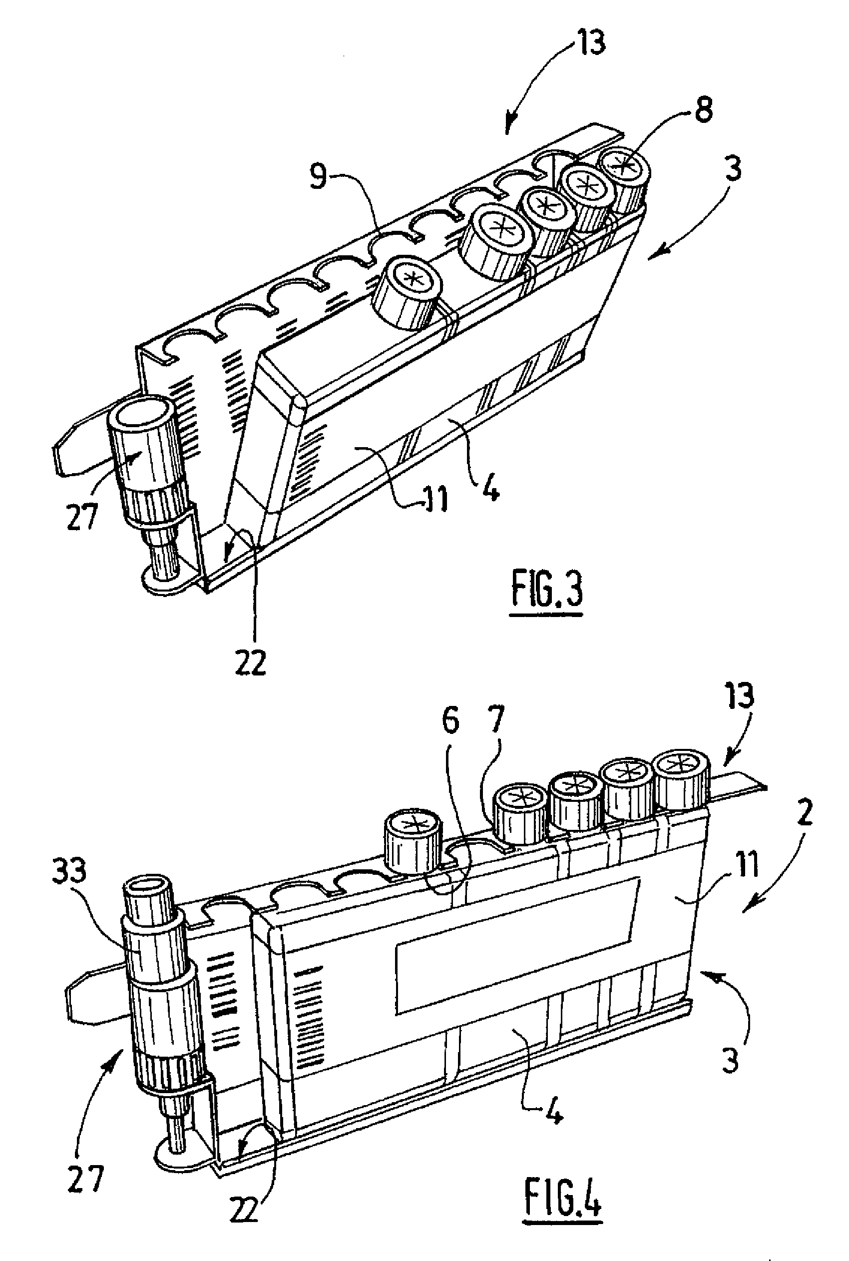
[0051]As shown more particularly in FIG. 1, the analysis unit 2 comprises a cartridge 3 for reagents, comprising five reagent receptacles 4 each containing a liquid reagent.

[0052]Each receptacle 4 is made of plastic as one piece and comprises a body 5 and a neck 6 formed integrally by means of blow-molding. The body 5 of each receptacle has a general rectangular shape viewed in section and comprises two substantially parallel longitudinal sides intended to co-operate with an analysis apparatus carrier and two transverse sides with a matching shape. The transverse sides of two adjacent receptacles directed towards each other rest against each other.

[0053]It must be noted that the neck 6 of each receptacle is equipped with a closing device 7 and is intended to cooperate with a notch with a matching shape provided on the analysis carrier. The closing device of each receptacle is formed by a cap 7, the skirt of which has, on its inner side, means for fixing by means of screwing or snap-...


PUM


Abstract

This analysis package comprises: a cartridge (3) for reactive products comprising several recipients (4) for reactive products arranged one above the other, wherein each recipient comprises a neck (6), wherein the neck of each recipient is provided with a closing device (7) and a plate (13) for receiving the cartridge (3), wherein the plate comprises a receptacle (22) which is open to the top for receiving the bases of the recipients (4) for reactive products which bases form the cartridge; and means for keeping the recipients for reactive products in position situated in distance from the receptacle, wherein the position keeping means are organized such that they cooperate with the necks of the recipients for reactive products when the bases of said recipients are received in the receptacle (22).

Description

BACKGROUND OF THE INVENTION[0001]The present invention concerns an analysis unit intended to be used in analysis apparatus.DESCRIPTION OF THE PRIOR ART[0002]The document EP 0 871 894 describes a first type of analysis unit. This analysis unit consists of a cartridge for reagents. According to this document, the cartridge comprises several reagent receptacles fixed to each other by means of connecting slides provided on the transverse sides of the receptacles. Each receptacle consists of a body formed by two half-shells obtained by means of plastic injection-molding and ultrasound-welding and a lid ultrasound-welded onto the opening defined by the half-shells. Moreover, each receptacle comprises two slides of matching shape which are molded integrally with the respective half-shells and are provided respectively on each of its transverse sides, each slide being intended to co-operate with a matching slide of an adjacent receptacle.[0003]The manufacture of these receptacles requires t...

Claims


Application Information

Patent Timeline
Patent Type & Authority Applications(United States)
IPC IPC(8): B01L9/06
CPCG01N2035/00524G01N35/1002G01N35/026B65D71/50B01L9/06B01L3/527B01L2200/025B01L2300/021B01L2300/044B01L2300/0809
Inventor ROUSSEAULERAT, OLIVIER
Owner IMMUNODIAGNOSTIC SYST FRANCE
Why Eureka
Try Eureka