
Bicycle shift control device

Inactive Publication Date: 2010-02-18
TIEN HSIN INDS
View PDF3 Cites 3 Cited by
  • Summary
  • Abstract
  • Description
  • Claims
  • Application Information

AI Technical Summary

Benefits of technology

[0008]The main objective of the present invention is to provide an improved bicycle shift control device in that a compact, ergonomic, and low air resistance bicycle shift control device is acquired.
[0014]The pushing member and the pulling rod move linearly. Therefore the present invention is compact. The cable lever has a U-shaped cross section and is in a shape of curve. The cable lever is easy to manipulate and mates the human factor. Furthermore the shape of the cable lever minimizes air resistance. The usage of release mechanism for down shift operation and that of cable lever for up shift operation make the rider easy to understand the operation.

Problems solved by technology

Therefore the response time for operation is affected.
The air resistance will affect the speed, and therefore this is disadvantageous for a cycling competition.

Method used


Image

  • Bicycle shift control device
  • Bicycle shift control device
  • Bicycle shift control device

Examples


Embodiment Construction

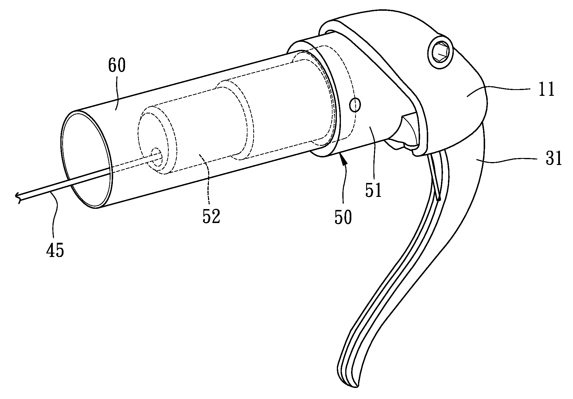
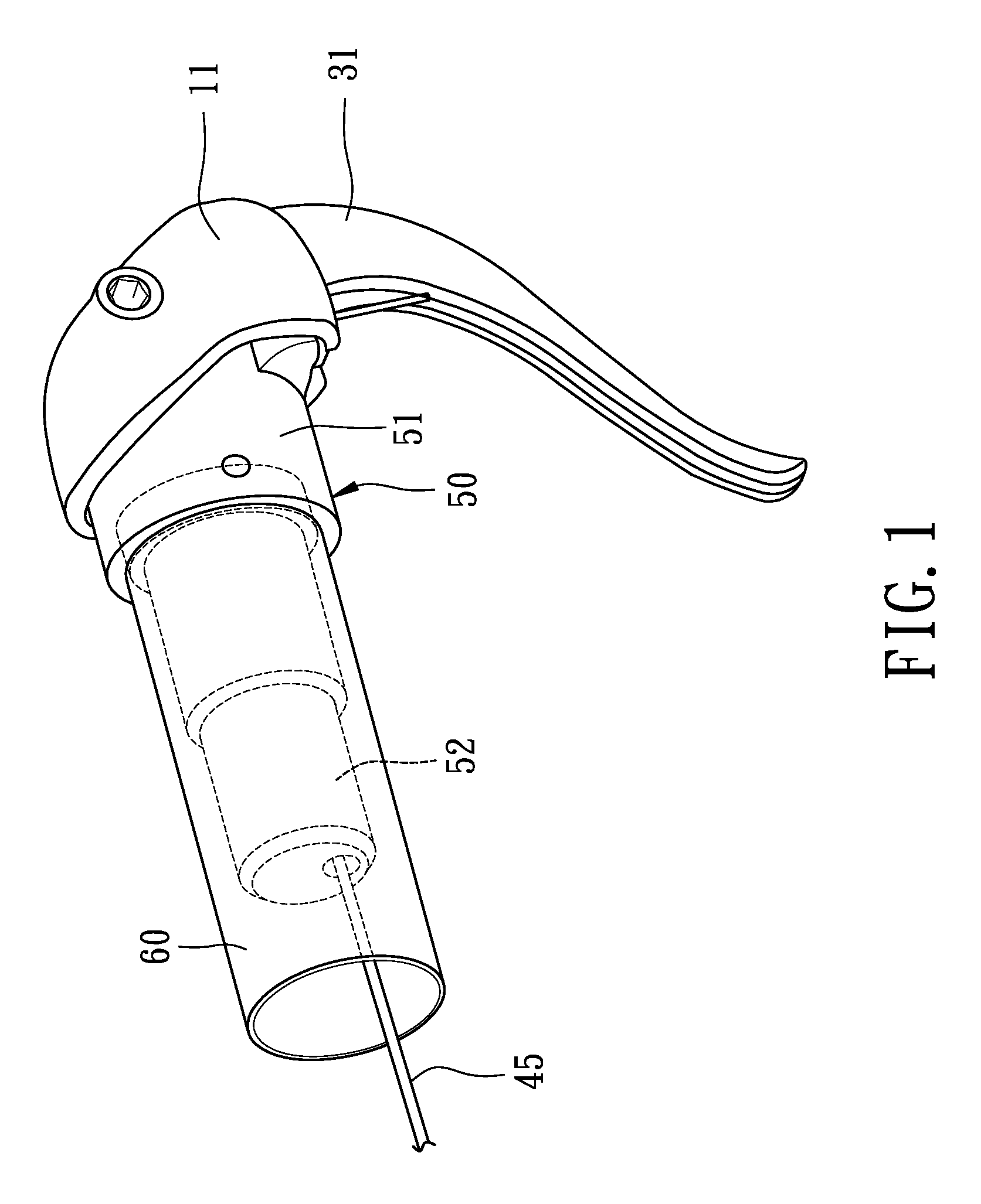
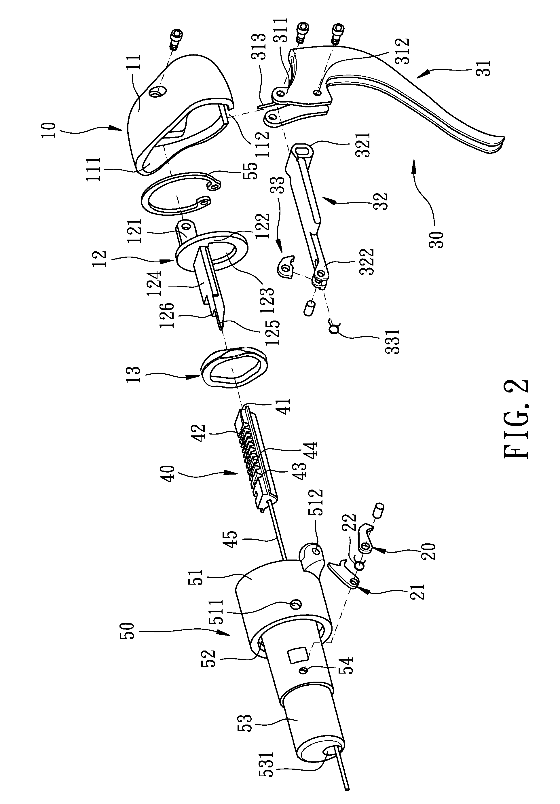
[0031]Referring to the drawings and initially to FIGS. 1-3, a bicycle shift control device in accordance with the present invention comprises a release mechanism 10, a pulling mechanism 30, a sliding base 40, and a housing 50. The release mechanism 10 and the pulling mechanism 30 are respectively connected to the sliding base 40 and partially received in the housing 50. The sliding base 40 is movable received in the housing 50 and connects to a cable 45 which is connected to a front / rear derailleur for activating the up shift operation or the down shift operation. The housing 50 is inserted into a handle bar 60 for partially concealing the bicycle shift control device.

[0032]Referring to FIGS. 2-4, the release mechanism 10 includes a release base 11 sleeved on the housing 50, a pushing member 12 connected to the release base 11 and received in the housing 50, a first pawl 20 pivotally mounted in the housing 50, and a main pawl 21 pivotally mounted in the housing 50 and corresponding ...


PUM


Abstract

A bicycle shift control device includes a release mechanism, a pulling mechanism, a sliding base connected to a cable adapted to be connected to a derailleur. The release mechanism includes a release base and a pushing member connected to a first pawl and a main pawl. The pulling mechanism includes a cable lever and a pulling rod connected to a second pawl. The sliding base has series of teeth for engaging with the first pawl, the main pawl, and the second pawl. When pulling the cable lever, the sliding base is driven to move by the second pawl to activate the up shift operation. When pressing the release base, the pushing member operates with the first pawl and the main pawl to activate the down shift operation.

Description

BACKGROUND OF THE INVENTION[0001]1. Field of the Invention[0002]The present invention relates to a shift device, and more particularly to a bicycle shift control device in that a compact, ergonomic, and low air resistance bicycle shift control device is acquired.[0003]2. Description of Related Art[0004]In general, a bicycle shift control device is mounted on a handle bar and connects to a bicycle front / rear derailleur via a cable. In an up shift operation, the bicycle front / rear derailleur is controlled by the bicycle shift control device to shift a chain from a small sprocket to a large sprocket. In a down shift operation, the bicycle front / rear derailleur is controlled by the bicycle shift control device to shift the chain from a large sprocket to a small sprocket.[0005]In triathlons and time trials, the handle bar is different from the general handle bar. The handle bar for triathlons and time trials includes a pair of side handle bars which are in a shape of airfoil, a pair of f...

Claims


Application Information

Patent Timeline
IPC IPC(8): F16C1/16
CPCY10T74/20426F16C1/16
Inventor CHIANG, DOUGLAS
Owner TIEN HSIN INDS
Features
  • Generate Ideas
  • Intellectual Property
  • Life Sciences
  • Materials
  • Tech Scout
  • Unparalleled Data Quality
  • Higher Quality Content
  • 60% Fewer Hallucinations
Learn More