Lubricating device and lubrication apparatus comprising said device

a technology of lubricating device and lubricating apparatus, which is applied in the direction of lubricating pumps, engine components, machines/engines, etc., can solve the problems of difficult distribution of lubricant quantity, and achieve the effect of low surface wear

Active Publication Date: 2010-02-18
LINCOLN GMBH
View PDF10 Cites 6 Cited by
  • Summary
  • Abstract
  • Description
  • Claims
  • Application Information

AI Technical Summary

Benefits of technology

[0024]It is further of advantage if the catch head comprises at least one catch roller stayed on a compression spring, in order to keep the surface wear as low as possible.
[0025]To avoid damaging the lubricating device, the configuration of the lubricating head and catch head can be arrestable relative to the securement plate, for example by means of snap latches.

Problems solved by technology

While this known lubricating device is reliable in terms of its function, however relatively expensive in production, the dosing of the quantity of lubricant to be delivered is difficult.

Method used


Image

  • Lubricating device and lubrication apparatus comprising said device
  • Lubricating device and lubrication apparatus comprising said device
  • Lubricating device and lubrication apparatus comprising said device

Examples


Embodiment Construction

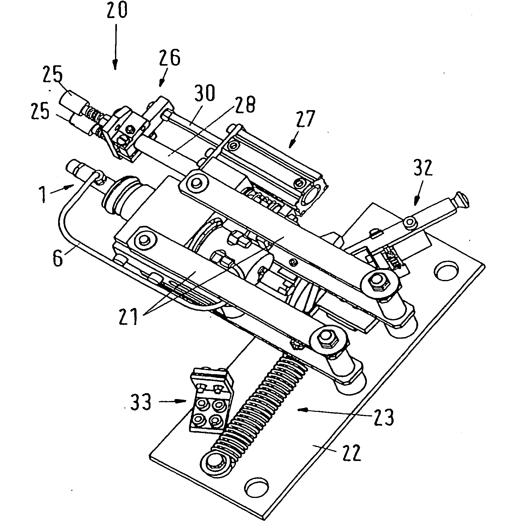
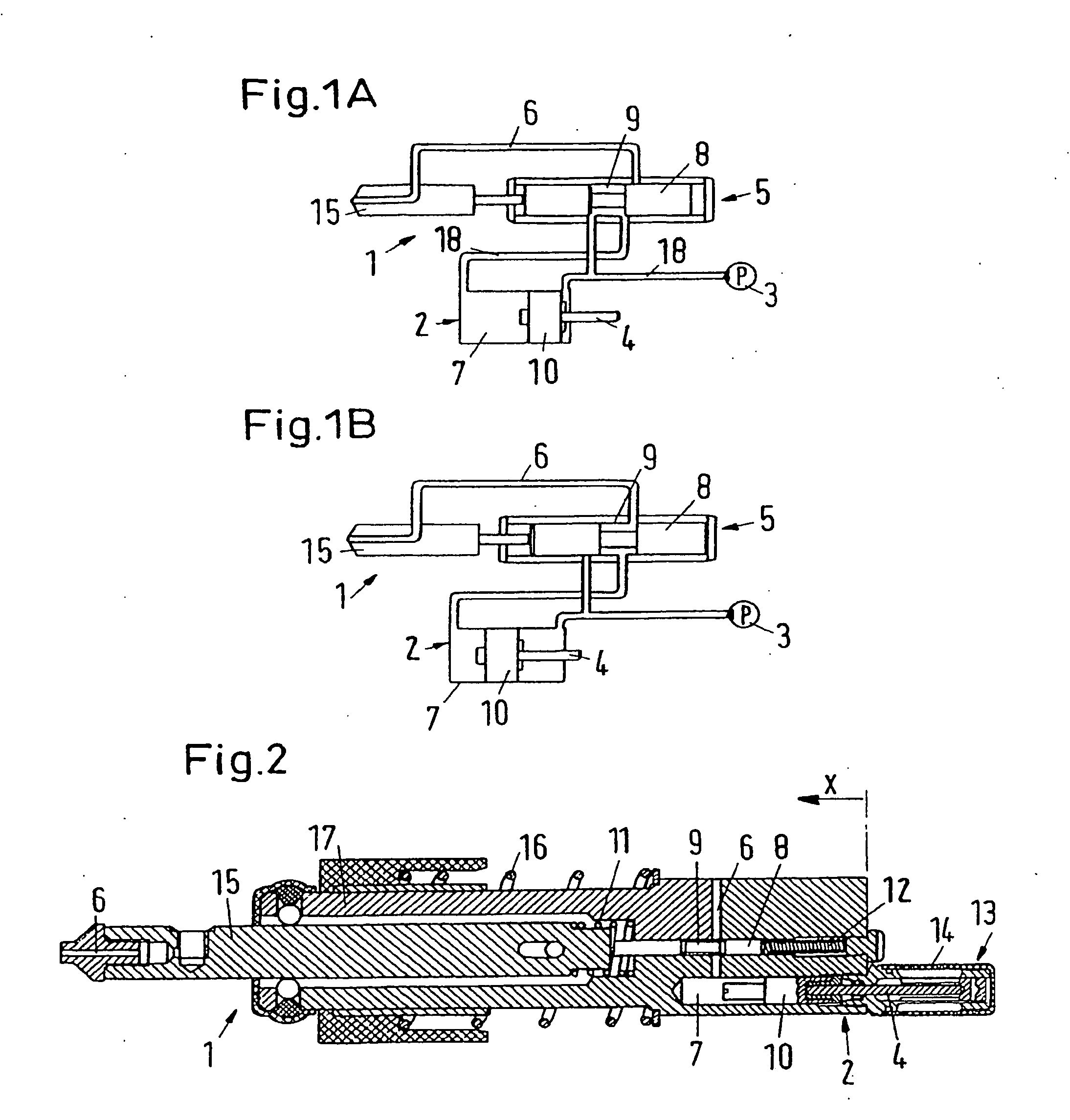
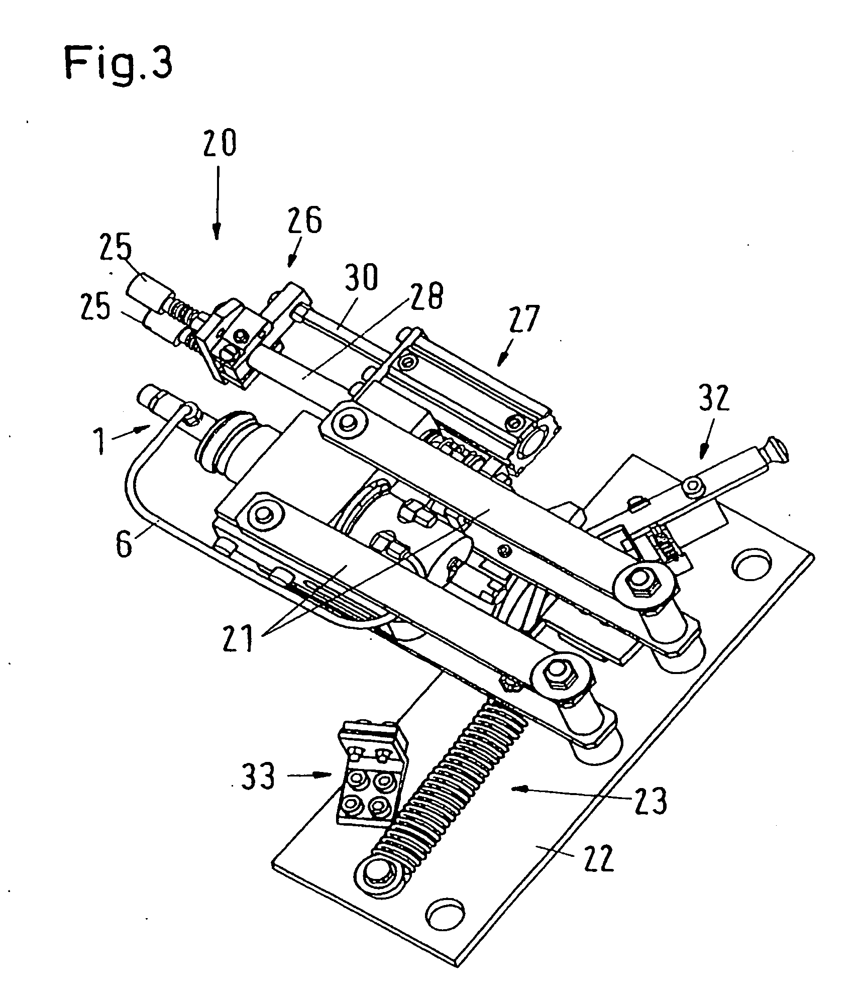
[0033]The lubricating device according to FIGS. 1A, 1B and 2 comprises a lubricating head 1 with a lubricant discharge body 15, in which a lubricant discharge channel 6 extends up to its lubricant discharge opening at the front tip. The lubricant discharge body 15 is pivoted axially displaceable in a base body 17 of the lubricating head 1 and its rearward end is stayed on a reset spring 11. With its rearward end area the lubricant discharge body 15 is in contact on the front end of a reversing piston 8, which with the lubricant discharge body 15 is axially displaceable coaxially in the base body 17 and which, in turn, on its rearward end is stayed on a reset spring 12. Due to a circumferential groove provided in its central region, the reversing piston 8 forms with the base body 17 an annular space 9, which, in the operating position depicted in FIG. 2, is fluidally connected, on the one hand, with a dosing chamber 7 of a dosing piston / cylinder configuration 2 screwed into the base ...


PUM


Abstract

The invention relates to a lubricating device, particularly for use in an apparatus which is used to lubricate mobile lubrication points e.g. on a rotating belt or chain belt. A lubricant discharge body of a lubricating head, which when lubricant is conveyed by a feed pump into a dosing chamber which is separated from the lubricant discharge channel, is placed in a front standby position and, counter to the effect of a restoring force, is moved into a locking and lubricant release position wherein the link between the pump and the dosing chamber is blocked by a reversing piston and the dosing chamber is fluidic ally connected to the lubricant discharge channel and a predefined volume of lubricant can be pumped out of the dosing chamber into the lubricant discharge channel. The lubricant discharge body cooperates with a reversing piston in such a way that the feed pump is fluidic ally connected to the dosing chamber of a dosing piston/cylinder arrangement via an annular area of the reversing piston when the lubricant discharge body is located in a front standby position, and such that the dosing chamber is fluidically connected to the lubricant discharge channel via the angular area when the lubricant discharge body is placed in a retracted position in which the lubricant is released. The reversing piston blocks the fluidic connection between the feed pump and the dosing chamber such that the amount of lubricant provided for discharge can be pumped out of the dosing chamber in the direction of the annular area by a dosing piston which is impinged upon by the feed pump.

Description

BACKGROUND OF THE INVENTION[0001]The invention relates to a lubricating device, in particular for application in an apparatus for lubricating migrating lubrication sites, for example on a roller or chain belt, in which a lubricant discharge body of a lubricating head, which, during the filling of lubricant by a feed pump into a dosing chamber separated from the lubricant discharge channel, is located in a forward standby position, and which can be displaced against the action of a reset force backwardly across a blocking and lubricant release position, in which, on the one hand, the connection between feed pump and dosing chamber is blocked by a reversing piston, and, on the other hand, the dosing chamber is in fluidic connection with the lubricant discharge channel, and a specifiable lubricant volume can be delivered from the dosing chamber into the lubricant discharge channel.[0002]In a known lubricating device the lubricant feed line from the feed pump terminates in a dosing cham...

Claims


Application Information

Patent Timeline
Patent Type & Authority Applications(United States)
IPC IPC(8): F16N7/14F16N7/36
CPCF16N7/36
Inventor PALUNCIC, ZDRAVKORODEMER, KARL
Owner LINCOLN GMBH
Why Eureka
Try Eureka