Foreign Matter or Abnormal Unsmoothness Inspection Apparatus and Foreign Matter or Abnormal Unsmoothness Inspection Method

a technology of unsmoothness and inspection apparatus, which is applied in the direction of mechanical roughness/irregularity measurement, mass spectrometer, and test/measurement of semiconductor/solid-state devices, etc., can solve the problem of difficult to ensure the spatial resolution of submicrons, take a long time to detect substrates, and less expected submicrons. problems, to achieve the effect of efficient analysis

Inactive Publication Date: 2010-02-18
CANON KK
View PDF9 Cites 4 Cited by
  • Summary
  • Abstract
  • Description
  • Claims
  • Application Information

AI Technical Summary

Benefits of technology

[0008]A principal object of the present invention is to provide a foreign matter or an abnormal unsmoothness inspection apparatus and a foreign or an abnormal unsmoothness inspection method, which are capable of reliably detecting foreign matter or abnormal unsmoothness, on the order of submicrons, on a substrate-like measuring object, together with its positional information, and efficiently performing analysis with reliability, without specifying and analyzing after collecting the foreign matter or abnormal unsmoothness from the measuring object. Particularly, an object of the present invention is to provide a foreign matter or an abnormal unsmoothness inspection method, which are capable of performing detection and analysis of minute organic foreign matter or abnormal unsmoothness.
[0009]The present inventors have found that it is possible to analyze the foreign matter or abnormal unsmoothness in such a manner that the foreign matter or abnormal unsmoothness on the surface of the measuring object is detected by measuring a degree of smoothness (or irregularity) of the surface of the measuring object, such as a substrate, and a dent is formed at a predetermined (specific) position distant from the foreign matter or abnormal unsmoothness and, thereafter, a mass spectrum is obtained at a predetermined position distant from the dent by a mass spectrum measuring means. Based on such findings, the present inventors have accomplished a foreign matter or an abnormal unsmoothness inspection apparatus, according to the present invention, capable of analyzing the foreign matter or abnormal unsmoothness, on the order of submicrons, in a short time.
[0018]The foreign matter or abnormal unsmoothness inspection apparatus and foreign matter or abnormal unsmoothness inspection method according to the present invention are capable of reliably detecting foreign matter or abnormal unsmoothness on the order of submicrons on a substrate-like measuring object, together with its positional information, and efficiently performing analysis with reliability, without specifying and analyzing, after collecting the foreign matter or abnormal smoothness from the measuring object. Particularly, the foreign matter or abnormal unsmoothness inspection apparatus and foreign matter or abnormal unsmoothness inspection method of the present invention are capable of performing detection and analysis of minute organic foreign matter or abnormal unsmoothness, with reliability.

Problems solved by technology

Therefore, it takes time to move the XY stage, so that it takes a long time to detect a substrate of, e.g., 200 nm×300 nm.
It is difficult to ensure a spatial resolution of submicrons, even when coherent light, or the like, is utilized.
For this reason, accuracy on the order of submicrons is less expected, so that it is difficult to identify a position of the minute object of 1 μm or less.
This makes it difficult to utilize a time-of-flight secondary ion mass spectrometer (TOF-SIMS), which is useful for analysis of the organic minute object.
Further, with respect to the minute object of 1 μm or less, an intermolecular force is dominant, so that a collecting operation is very difficult.
Even if the minute object can be collected, it is further difficult to fix the minute object at a desired position.

Method used


Image

  • Foreign Matter or Abnormal Unsmoothness Inspection Apparatus and Foreign Matter or Abnormal Unsmoothness Inspection Method
  • Foreign Matter or Abnormal Unsmoothness Inspection Apparatus and Foreign Matter or Abnormal Unsmoothness Inspection Method
  • Foreign Matter or Abnormal Unsmoothness Inspection Apparatus and Foreign Matter or Abnormal Unsmoothness Inspection Method

Examples


embodiment

[0046]The foreign matter inspection apparatus of the present invention will be specifically described below, with reference to the drawing, but the scope of the present invention is not limited thereto.

[0047]In this embodiment, a nanoindenter apparatus (“Triboindenter”, manufactured by Hysitron, Inc.) having an atomic force microscope (AFM) function, and a TOF-SIMS (“TRIFT III”, manufactured by ULVAC-PHI, Inc.) were used.

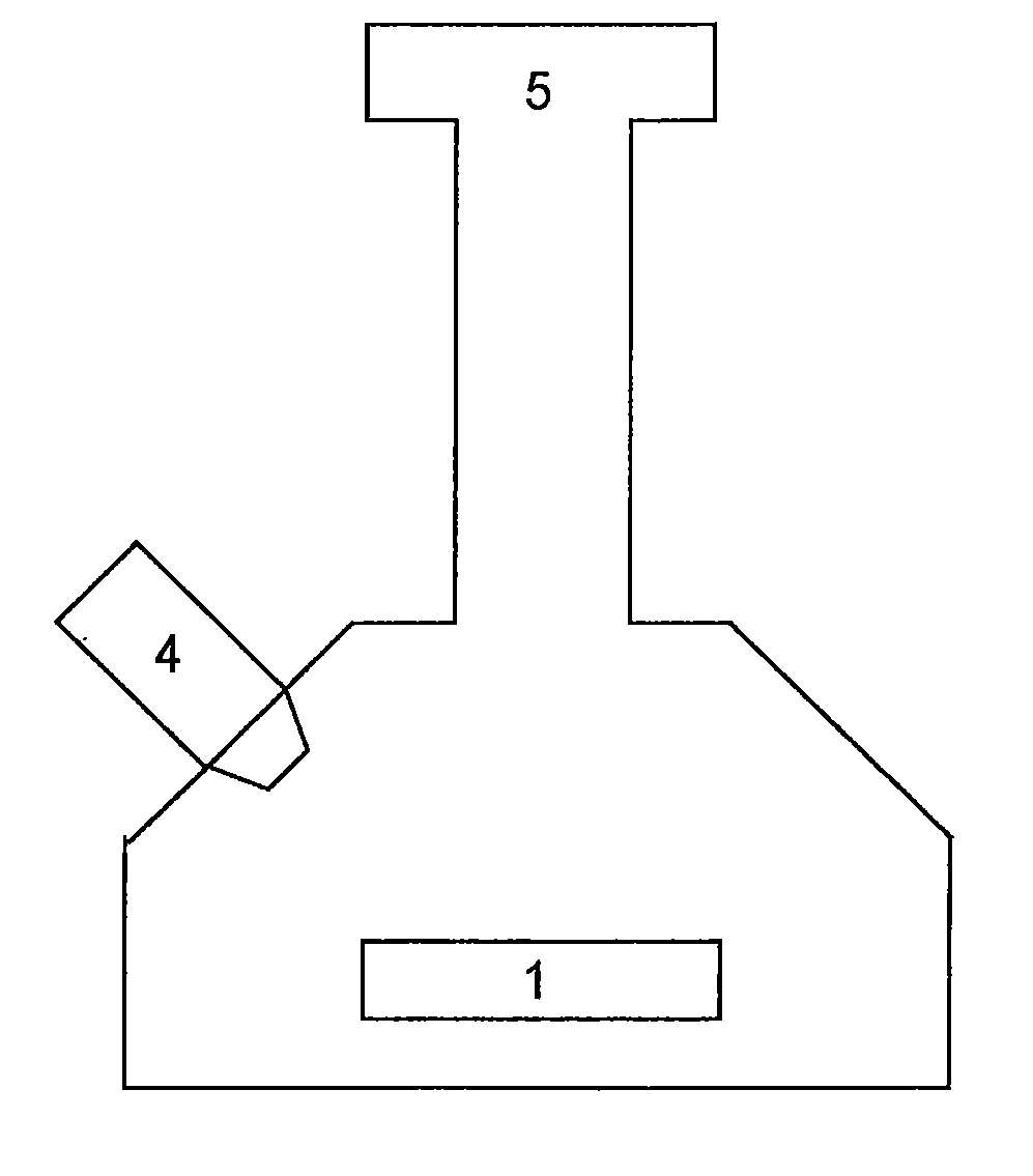
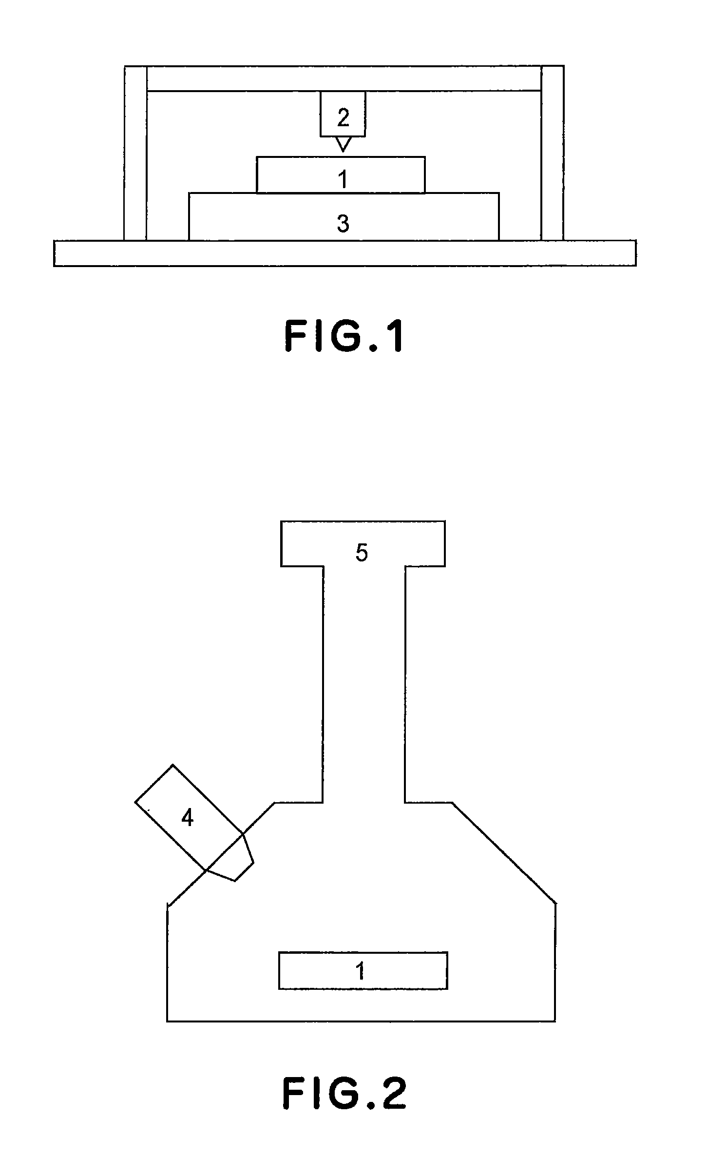
[0048]As an object to be measured, a sample was prepared by depositing a polystyrene fine particle having a diameter of 0.5 μm on a surface of an about 20-μm epoxy resin film formed on a silicon wafer. This sample was used, and the polystyrene fine particle was detected. On the epoxy resin film spaced at a position distant from the polystyrene fine particle by 5 μm, a dent was formed having a depth of about 2 μm. In the TOF-SIMS (TRIFT III), Ga+ ions were used as primary ions, and the measuring object was impacted with the primary ions in an area (50 μm×50 μm), in w...


PUM


Abstract

A foreign matter detecting apparatus includes a detecting device for detecting foreign matter by measuring smoothness of a surface of an object undergoing measurement, a marking device for providing a dent on the surface of the object with a predetermined horizontal distance from the foreign matter detected by the detecting device, and a mass spectrum measuring device for irradiating and scanning a small area with a primary ion beam, as a part of the object, including the foreign matter and the dent, so as to measure a mass spectrum of secondary ions emitted from the foreign matter located at a position within a predetermined horizontal distance from the dent.

Description

[0001]This is a divisional application of copending U.S. patent application Ser. No. 12 / 036,745, filed on Feb. 25, 2008.[0002]This application also claims priority from Japanese Patent Application No. 2007-051586, filed Mar. 1, 2007, which is hereby incorporated by reference herein.FIELD OF THE INVENTION AND RELATED ART[0003]The present invention relates to a foreign matter or an abnormal unsmoothness inspection apparatus for identifying a position of foreign matter deposited on, or abnormal unsmoothness at, a surface of a wafer, a glass substrate, or the like, and for analyzing a composition of the foreign matter or abnormal unsmoothness, particularly, a foreign matter or an abnormal unsmoothness inspection apparatus capable of detecting foreign matter or abnormal unsmoothness on the order of 1 μm or less. The present invention also relates to a foreign matter or an abnormal unsmoothness inspection method using the foreign matter or the abnormal unsmoothness inspection apparatus.[0...

Claims


Application Information

Patent Timeline
Patent Type & Authority Applications(United States)
IPC IPC(8): H01J49/26G01N3/48
CPCG06F11/0721G06F11/0766Y10T428/30H01J49/0036H01J49/0463H01J49/0031B82Y35/00H01L22/00
Inventor JINDAI, KAZUHIROYOKOI, HIDETO
Owner CANON KK
Why Eureka
Try Eureka