Trichromatic field-emission display and phosphors thereof

Inactive Publication Date: 2010-02-18
LO WEI HUNG
View PDF4 Cites 4 Cited by
  • Summary
  • Abstract
  • Description
  • Claims
  • Application Information

AI Technical Summary

Benefits of technology

[0016]The present invention has been accomplished under the circumstances in view. The purpose of the present invention is to provide a trichromatic field-emission display and phosphors thereof to eliminate the aforesaid drawbacks.
[0017]Firstly, the present invention provides a trichromatic field-emission display and phosphors thereof to create an internal vacuum gap in the CNT-FED display without equipping any electronic devices.
[0018]Secondly, the present invention provides a trichromatic field-emission display and phosphors thereof to improves the luminance of CNT-FED display and enhances anode plate binding strength.
[0019]To achieve the goals of the present inventio

Problems solved by technology

However, this structure of picture tube still has drawbacks: 1. High voltage applying, and professional X-ray radiation protection is necessary; 2. High fire risk due to high voltage applying in a picture tube; 3. Brightness difference upon striking of electron beam against different phosphor spots can cause tired eyes.
However, LCD and PDP are inferior to CRT in many other parameters, such as 1.
They have a high manufacturing cost, and every image component requires a specific memory; 2. They are temperature sensitive.
LCD will stop functioning and PDP will lower its luminance when the operating temperature is inap

Method used


Image

  • Trichromatic field-emission display and phosphors thereof
  • Trichromatic field-emission display and phosphors thereof
  • Trichromatic field-emission display and phosphors thereof

Examples


Example

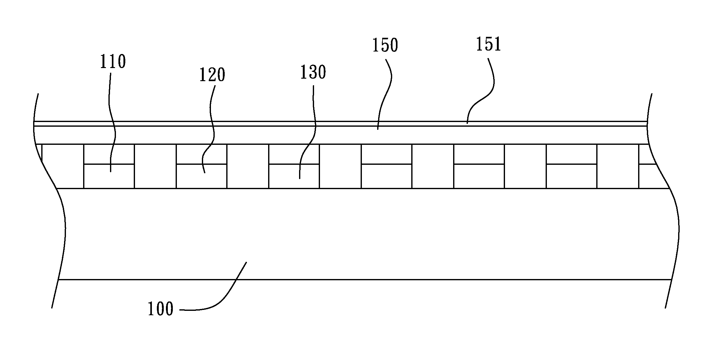
[0024]At first, the main object of the present invention is to eliminate the drawbacks of the aforesaid prior art phosphor screen. FIG. 3 illustrates a cross-sectional view of carbon nano-tube field-emission display according to the present invention. As illustrated, this trichromatic field-emission display comprises a cathode plate 100, three cathode electroluminescent phosphor screens 110, 120, 130, and an anode plate 150.

[0025]The anode plate 150 has a transparent oxide thin film 151 bonded to the photo gate electrode thereof. Electron sources emitted by the photo gate electrode of the cathode plate 100 strike the cathode electroluminescent phosphor screens 110, 120, 130, causing the electric field in the gap between the cathode plate 100 and the anode plate 150 to be changed, characterized in that the cathode electroluminescent phosphor screens 110, 120, 130, made of an excitable rare earth element, are assured with high stability and uniformity luminance when they are excited b...


PUM


Abstract

A trichromatic field-emission display is disclosed to include a cathode plate, three cathode electroluminescent phosphor screens and an anode plate, the anode plate having a transparent oxide thin film bonded to the photo gate electrode thereof, electron sources emitted by the photo gate electrode of the cathode plate striking the cathode electroluminescent phosphor screens to cause change of the electric field in the gap between the cathode plate and the anode plate. The cathode electroluminescent phosphor screens are made of an excitable rare earth element, assuring high stability and uniformity of luminous brightness when excited by an electron beam.

Description

BACKGROUND OF THE INVENTION[0001]1. Field of the Invention[0002]The present invention relates to a device message display technology, and more particularly to a novel combination display combining a vacuum fluorescent display technique that uses carbon nano-tubes (CNTs) as field emitters to generate sufficient energy electron beams for striking a light emitting surface in a glass casing. This combination is called CNT-FED display. FED anode plate is realized in the form of RGB inorganic cathode electroluminescence phosphor.[0003]2. Description of the Related Art[0004]Starting from the early 40's of the 20th century, cathode ray tube (CRT) has been used as independent electronic message display means. FIG. 1 illustrates a conventional CRT field-emission display screen architecture. In the photoelectric system inside the glass tube (picture tube), three hot cathodes are arranged. An electron beam moves back and forth through a meshed material 5 to strike the phosphor onto the inner su...

Claims


Application Information

Patent Timeline
IPC IPC(8): H01J1/62
CPCC09K11/7767C09K11/7774H01J29/20H01J31/123H01J2329/18C09K11/7784C09K11/77742
Inventor NAUM, SOSHCHINLO, WEI-HUNGTSAI, CHI-RUEI
Owner LO WEI HUNG
Why Eureka
Try Eureka