Light Emitting Diode Driving Apparatus

a technology of light-emitting diodes and driving apparatuses, which is applied in the direction of instruments, light sources, electroluminescent light sources, etc., can solve the problems of large power loss of low-cost series regulator type control circuits with a small circuit scale, increased mounting area, and increased cost of circuits

Active Publication Date: 2010-02-18
SATURN LICENSING LLC
View PDF4 Cites 6 Cited by
  • Summary
  • Abstract
  • Description
  • Claims
  • Application Information

AI Technical Summary

Benefits of technology

[0006]However, the forward bias voltage of a light emitting diode (hereinafter called “voltage Vf”) varies greatly, so that even light emitting diodes of the same kind have a difference in voltage Vf. In case where light emitting diodes are driven on a constant controlled voltage, therefore, a large current flows when the voltage Vf is low, and a small current flows when the voltage Vf is high, so that the luminance of light obtained from the backlight device does not become constant. To control the luminance without being influenced by a variation in voltage Vf, a technique of driving light emitting diodes on a constant current has been employed. In the past, one constant current control circuit is used for a line of light emitting diodes connected in series. Therefore, driving multiple lines of light emitting diodes needs drive circuits each formed as a constant current control circuit, which are equal in number to the lines. A low-cost series regulator type control circuit with a small circuit scale suffers a large power loss originating from the difference between the supply voltage and a voltage Vfs (which is the sum of the individual voltages Vf of a plurality of light emitting diodes connected in series). When a switching regulator type control circuit which has a small power loss is used, it has a large circuit scale, thus bringing about a problem such that the mounting area becomes larger and the cost for the circuit becomes higher.
[0007]Thus, it is desirable to provide a light emitting diode driving apparatus at a low circuit cost, which can let an equal current flow to individual light emitting diodes in multiple lines of light emitting diodes.
[0010]The embodiment of the present invention can provide a light emitting diode driving apparatus that has one or more current distribution coils disposed between the switching converter and the plurality of serial light emitting diode lines to let the current flow in the direction of canceling out a magnetic flux generated by the first winding and a magnetic flux generated by the second winding each other, so that an equal current can flow in each of multiple lines of light emitting diodes.

Problems solved by technology

A low-cost series regulator type control circuit with a small circuit scale suffers a large power loss originating from the difference between the supply voltage and a voltage Vfs (which is the sum of the individual voltages Vf of a plurality of light emitting diodes connected in series).
When a switching regulator type control circuit which has a small power loss is used, it has a large circuit scale, thus bringing about a problem such that the mounting area becomes larger and the cost for the circuit becomes higher.

Method used


Image

  • Light Emitting Diode Driving Apparatus
  • Light Emitting Diode Driving Apparatus
  • Light Emitting Diode Driving Apparatus

Examples


first embodiment

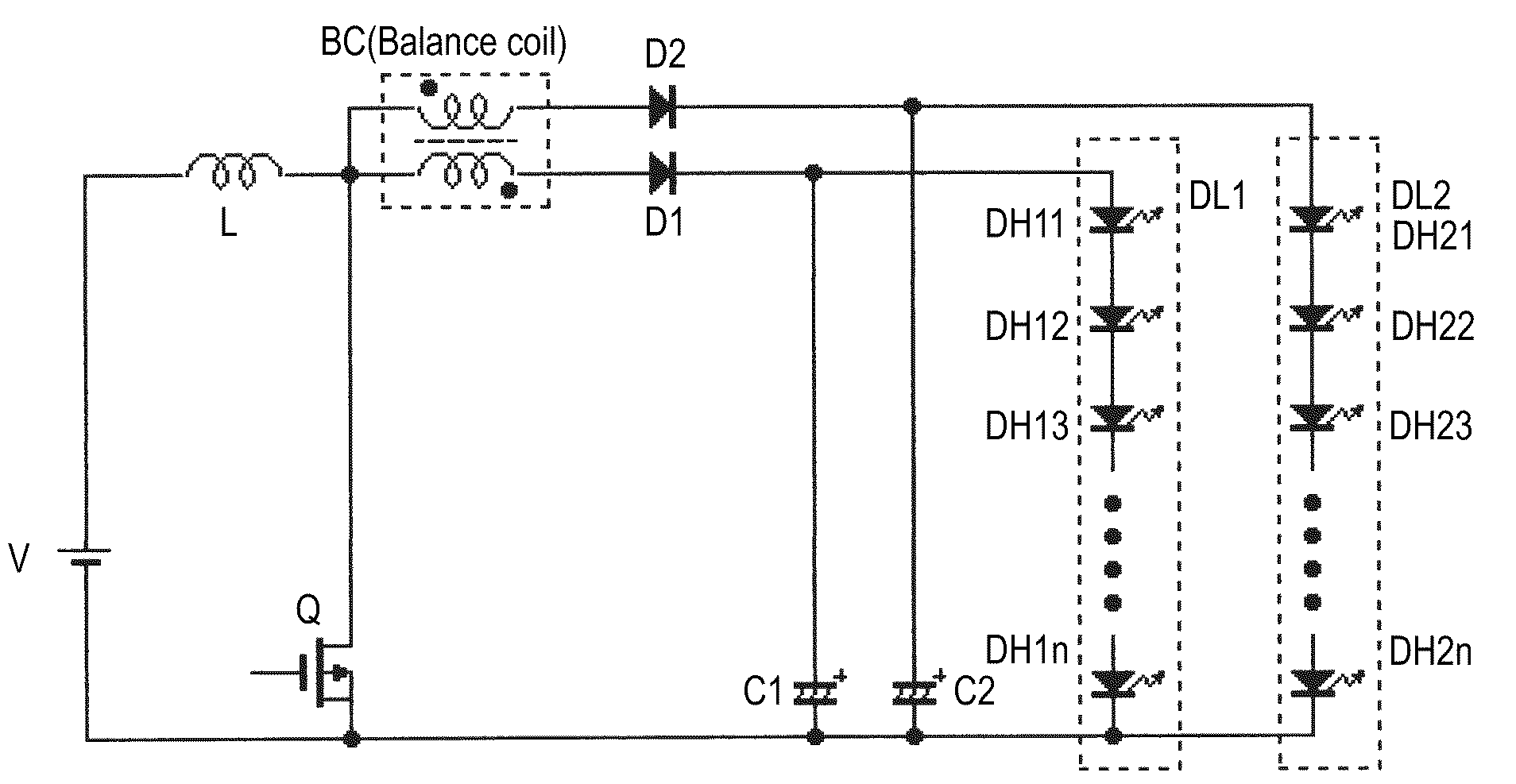
[0028]That is, the light emitting diode driving apparatus has a single current distribution coil BC whose first and second windings have one ends connected to the switching converter. Here, one end of the first winding is the start of turning, and one end of the second winding is the end of turning. That is, the first winding and the second winding may be changed from one to the other as long as both windings are connected in such a way as to cancel out magnetic fluxes each other when the current is let to flow from one end of the first winding and the current is let to flow from one end of the second winding. The expression “other end” means a side different from the one end. The meanings of the expressions “one end” and “other end” are the same in the following description.

[0029]The light emitting diode driving apparatus has the serial light emitting diode line DL1 (first serial light emitting diode line) connected to the other end of the first winding of the current distribution...

second embodiment

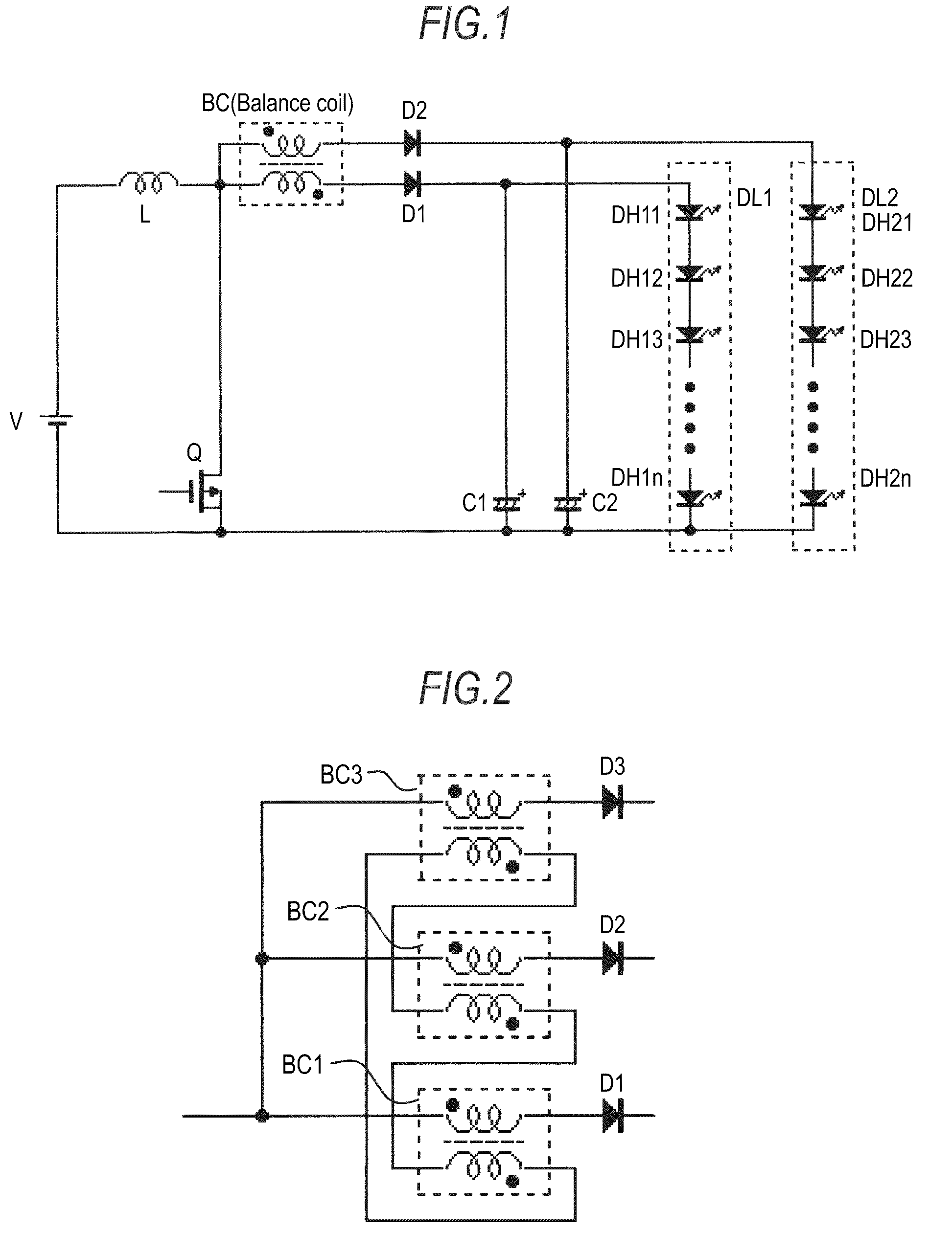
[0035] one end of the first winding of the current distribution coil BC1 (first current distribution coil), one end of the first winding of the current distribution coil BC2 (second current distribution coil), and one end of the first winding of the current distribution coil BC3 (third current distribution coil) are connected to one another. The node of the mutual connection is connected to the switching converter. Here, the expression “one end” does not mean that it is specified to be one of the start of turning of the winding and the end of turning of the winding. It is to be noted that the winding directions of the first winding and the second winding of the same current distribution coil in the current distribution coils BC1 to BC3 are important. For example, even if the directions of the start of turning and the end of turning of both the first and second windings of each current distribution coil are changed from one to the other, the currents flow in the first and second wind...

third embodiment

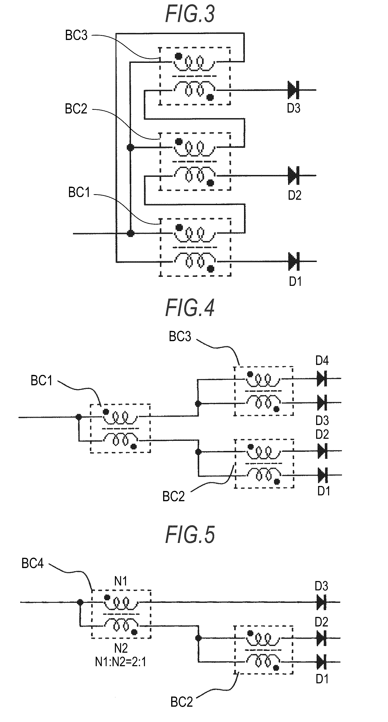
[0042] one end of the first winding of the current distribution coil BC1 (first current distribution coil), one end of the first winding of the current distribution coil BC2 (second current distribution coil), and one end of the first winding of the current distribution coil BC3 (third current distribution coil) are connected to one another. The node of the mutual connection is connected to the switching converter. Further, the other end of the first winding of the current distribution coil BC1 is connected to one end of the second winding of the current distribution coil BC2. Moreover, the other end of the first winding of the current distribution coil BC2 is connected to one end of the second winding of the current distribution coil BC3. The other end of the first winding of the current distribution coil BC3 is connected to one end of the second winding of the current distribution coil BC1. This connection allows the magnetic fluxes generated in the current distribution coil BC1 t...


PUM


Abstract

A light emitting diode driving apparatus includes: a switching converter having an inductor and a switching device; a plurality of serial light emitting diode lines each having a plurality of light emitting diodes connected in series; a plurality of rectifier diodes respectively connected in series to the plurality of serial light emitting diode lines; a plurality of capacitors respectively connected to nodes between the serial light emitting diode lines and the rectifier diodes for smoothing a voltage; and one or more current distribution coils disposed between the switching converter and the plurality of serial light emitting diode lines to let a current flow in a direction of canceling out a magnetic flux generated by a first winding and a magnetic flux generated by a second winding each other, thereby making currents flowing in the serial light emitting diode lines equal to each other.

Description

BACKGROUND OF THE INVENTION[0001]1. Field of the Invention[0002]The present invention relates to a light emitting diode driving apparatus.[0003]2. Description of the Related Art[0004]Recently, liquid crystal devices using liquid crystals are widely used in a variety of industrial fields. Such a liquid crystal device employs a structure where a backlight device is provided on the back side of a liquid crystal panel to irradiate light to the liquid crystal panel. In the past, a cold cathode fluorescent tube (CCFL) is frequently used as a backlight device. In the recent years, however, light emitting diodes (LEDs) are used as well. In case of using light emitting diodes, the light emitting diodes are connected in series, and a favorable drive voltage is applied across a plurality of light emitting diodes connected in series. Further, there is a technique of arranging plural lines of light emitting diodes connected in series to cause the light emitting diodes to emit light over a wide a...

Claims


Application Information

Patent Timeline
Patent Type & Authority Applications(United States)
IPC IPC(8): H05B37/02
CPCH05B33/0815H05B45/38
Inventor YAMANE, MITSURUOYAMA, YOSHIKI
Owner SATURN LICENSING LLC
Why Eureka
Try Eureka