Asymmetric Radome For Phased Antenna Arrays

a phased antenna array and asymmetric technology, applied in the direction of antenna details, protective material radiating elements, antennas, etc., can solve the problems of signal phase and power in a non-uniform manner, signal quality and therefore performance of airborne radar systems that use active and passive phased arrays can be marginalized, and errors in resolution and direction are produced

Inactive Publication Date: 2010-02-18
NORTHROP GRUMMAN SYST CORP
View PDF11 Cites 69 Cited by
  • Summary
  • Abstract
  • Description
  • Claims
  • Application Information

AI Technical Summary

Problems solved by technology

Specifically, the signal quality and therefore performance of airborne radar systems that use active and passive phased arrays can be marginalized by the aerodynamic contouring of radomes of conventional design used to protect the antennas from the environment.
External influences such as the contour of the radome can alter the signal phase and power in a non-uniform manner such that phase and power differences are introduced to the wave between the measurement antenna pairs that are not consistent with the unperturbed wave.
Errors in resolution and direction are produced when unaccounted ray phase and power differences are processed.
These radome induced phenomenon can be large, resulting in computation errors that cause a loss of DF accuracy and SAR resolution.
A “look-up” table can be used by the signal processor to correct some phase anomalies, but the degree of correction...

Method used


Image

  • Asymmetric Radome For Phased Antenna Arrays
  • Asymmetric Radome For Phased Antenna Arrays
  • Asymmetric Radome For Phased Antenna Arrays

Examples


Embodiment Construction

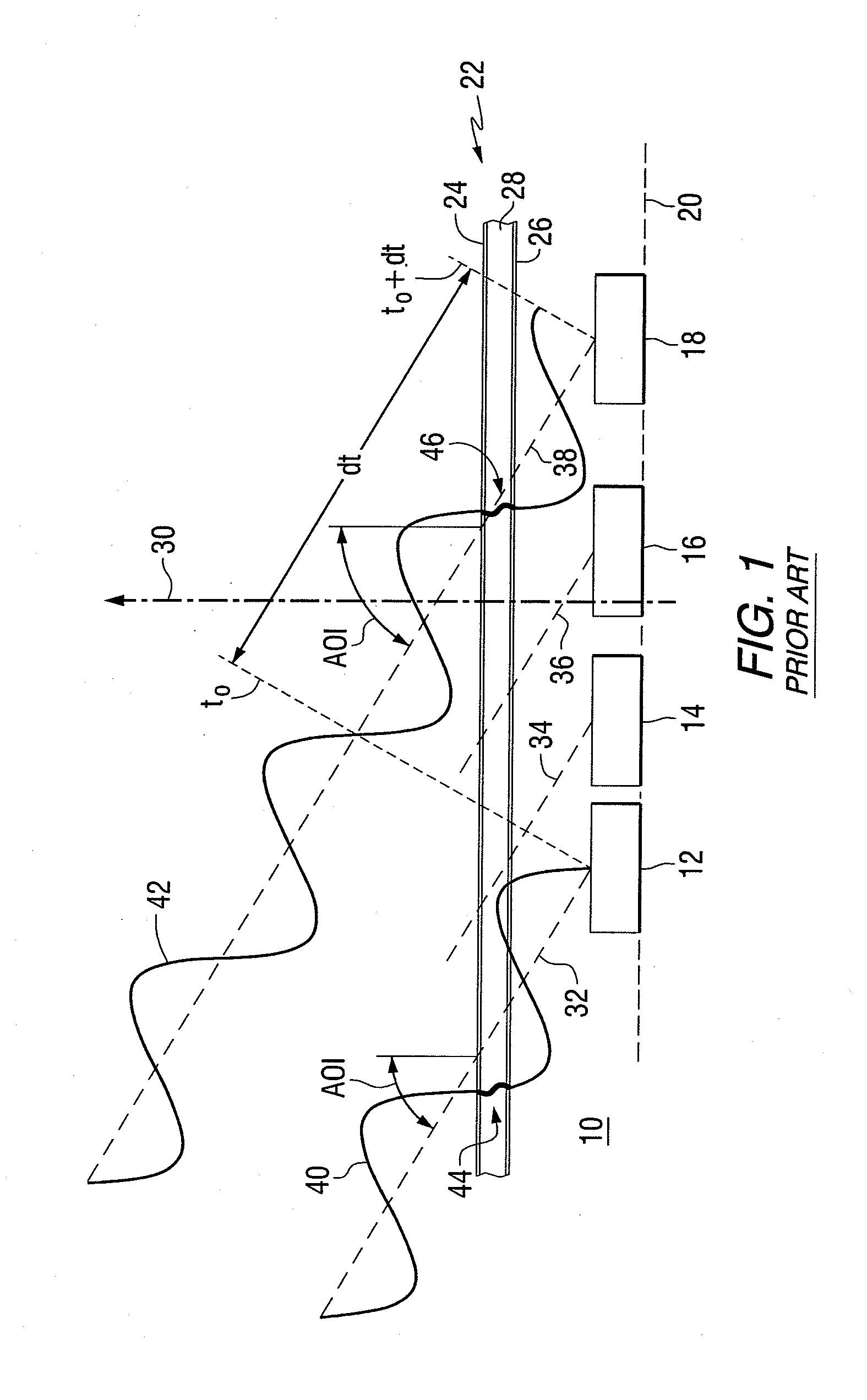
[0016]Referring to the drawings, FIG. 1 is a cross-sectional view of an antenna array assembly 10 including a plurality of antenna elements 12, 14, 16 and 18 mounted on a common plane 20 and having a flat A-sandwich radome 22. The radome includes an outer layer, or skin, 24 and an inner layer, or skin, 26 positioned on opposite sides of a core layer 28. The skins and core each have a uniform thickness. In common designs, the thin skins are a relatively dense material, such as plastic or laminated fiber reinforced plastic, and the core layer is a thicker low density material, having for example a foam or honeycomb structure.

[0017]Arrow 30 represents the array bore sight direction. In this example, individual rays of a single incoming signal, represented by lines 32, 34, 36 and 38, impinge on the radome at a uniform angle of incidence (AOI). The incoming signal is assumed to have a planar wave front and as such has equal phase at all points on the wave front. Consider, for example, po...


PUM


Abstract

An antenna assembly comprises a plurality of antenna elements arranged in an array, and a radome for protecting the antenna elements, wherein the radome has a thickness that changes across a field of view to normalize insertion phase delay differences in an incoming signal passing through the radome and received by the antenna elements.

Description

STATEMENT OF GOVERNMENT INTEREST[0001]This invention was made under Contract No. N00019-04-C-0005. The United States Government has rights in this invention under the contract.FIELD OF THE INVENTION[0002]This invention relates to antenna assemblies and, more particularly, to radomes for use with radar systems using active and / or passive antenna arrays.BACKGROUND OF THE INVENTION[0003]Radome design and configuration are important elements affecting the overall performance of high frequency radar applications where signal phase and transmission uniformity is required for optimum system performance. Specifically, the signal quality and therefore performance of airborne radar systems that use active and passive phased arrays can be marginalized by the aerodynamic contouring of radomes of conventional design used to protect the antennas from the environment. Antenna system applications of interest include active and passive phased arrays that employ a plurality of antenna elements arrang...

Claims


Application Information

Patent Timeline
IPC IPC(8): H01Q1/42
CPCH01Q1/40H01Q21/08H01Q21/06H01Q1/421
Inventor PETER, MICHAEL J.CORCORAN, PETER M.
Owner NORTHROP GRUMMAN SYST CORP
Why Eureka
Try Eureka