Fixation device for a portable drilling unit

Inactive Publication Date: 2010-02-18
NOVATOR
View PDF8 Cites 14 Cited by
  • Summary
  • Abstract
  • Description
  • Claims
  • Application Information

AI Technical Summary

Benefits of technology

[0011]According to still another aspect of the invention the piston of the clamping mechanism, which axially displaces the pressure cylinder for urging the locking balls into their locked position in the groove of the guide bushing, is a double-acting pneumatic sleeve-like piston. Circumferentially spaced compression springs may act on the side of the piston which displaces the piston in a ball-locking direction, and pressurized air is applied to the opposite side of the piston to displace the latter against the action of the springs so as to release the balls from their locking position in the bushing groove. Since the piston is a double-action pneumatic piston, pressureized air introduced into a chamber on the spring side of the piston may be utilized to increas

Problems solved by technology

The use of a template with a portable or hand tool can be problematic due to the inherent positioning flexibility and degrees of freedom of motion of the tool which now must be constrained to follow the template pattern.
If, in case of clamping mechanisms having a single guide bushing, the rotating cutting tool for any reason is jammed in the workpiece, this could result in an undesired rota

Method used


Image

  • Fixation device for a portable drilling unit
  • Fixation device for a portable drilling unit
  • Fixation device for a portable drilling unit

Examples


Embodiment Construction

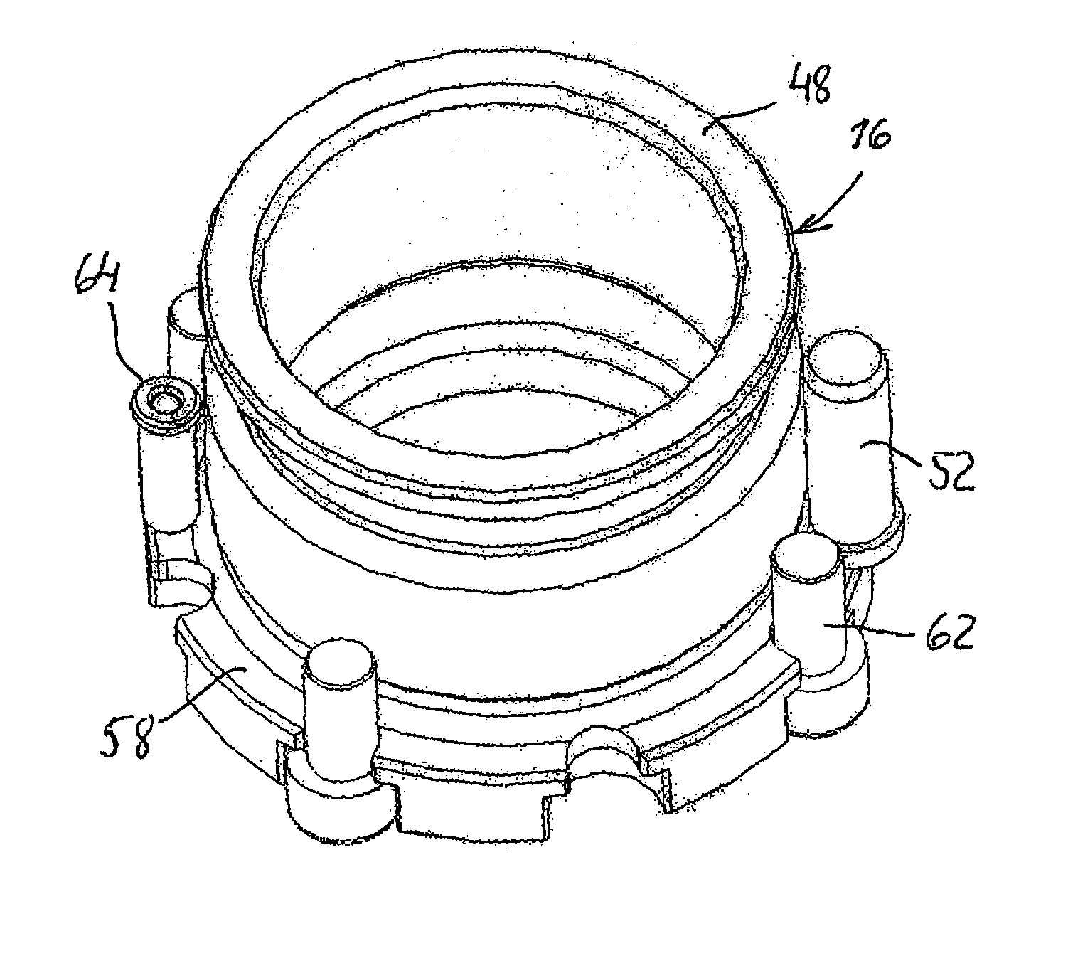
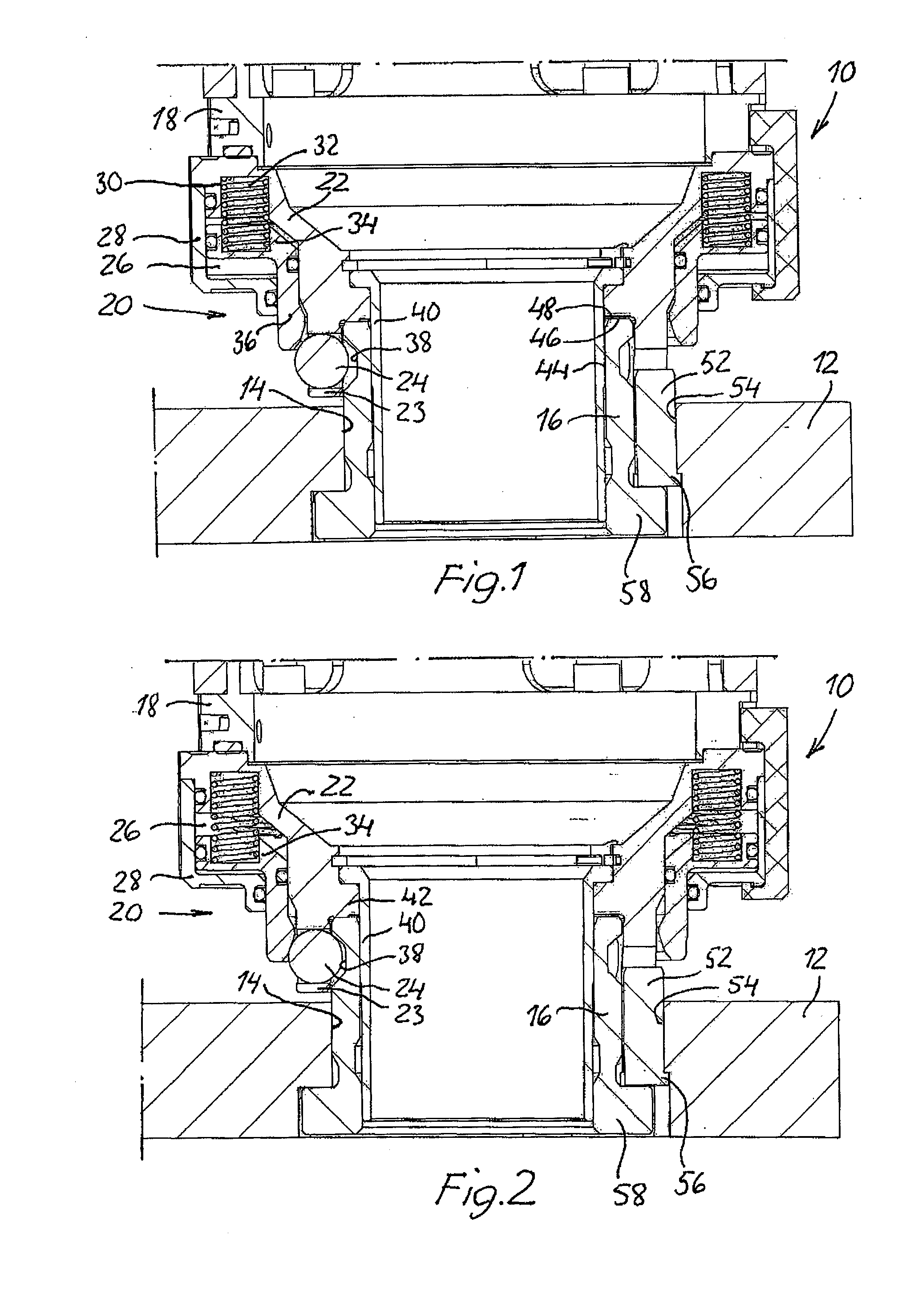
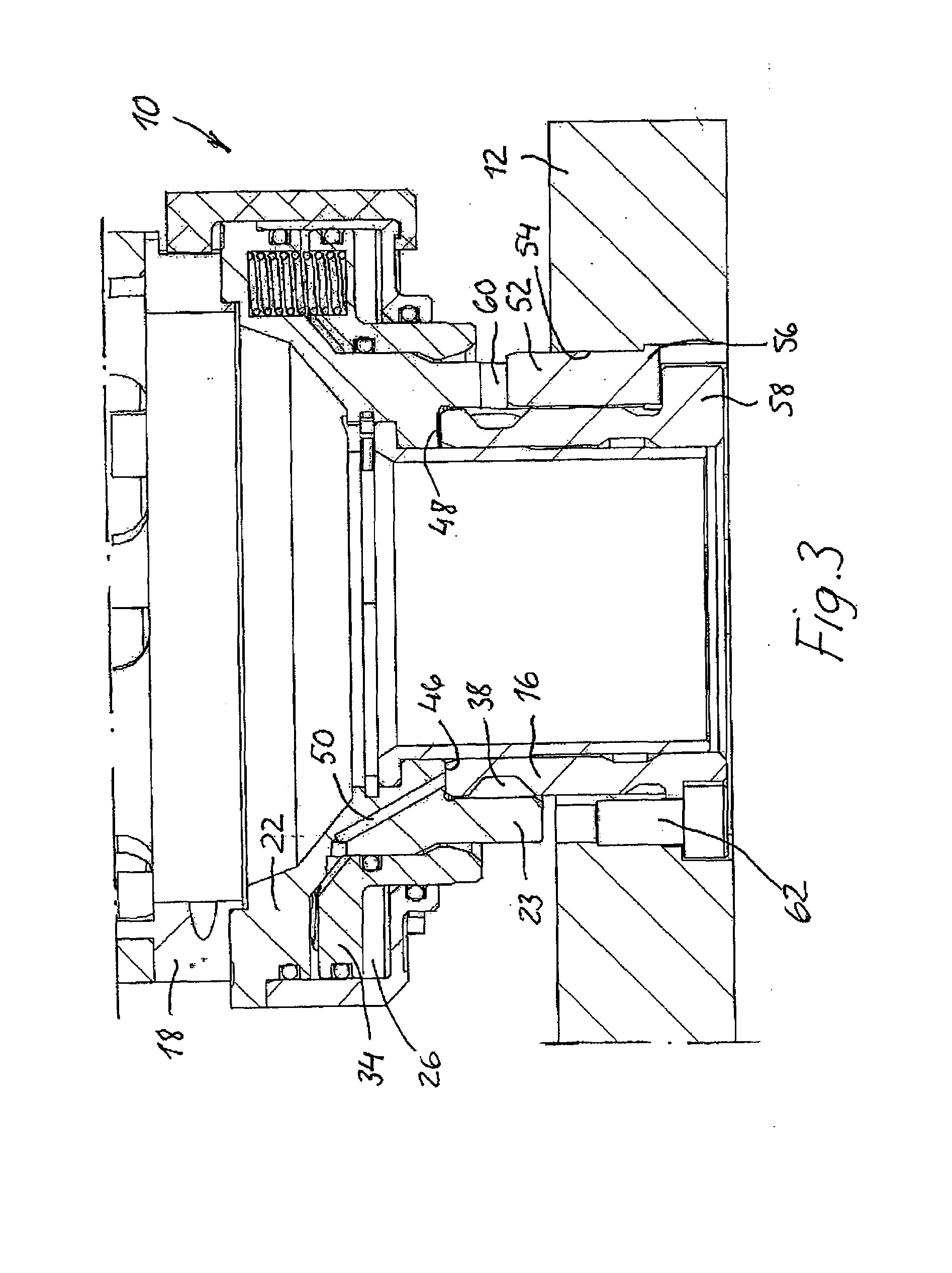
[0020]FIGS. 1-3 disclose a clamping mechanism 10 for detachably connecting an orbital drilling unit (not shown) to a drill template 12 which is attached adjacent to a workpiece (not shown), e.g. a structural component of an aircraft, and provided with a plurality of predrilled guide holes 14 located in a predetermined pattern corresponding to the positions of the holes to be drilled in the workpiece. Each guide hole 14 houses a hollow guide bushing 16 to which the drilling unit is to be fixedly secured by means of the clamping mechanism 10 during a hole machining process.

[0021]The clamping mechanism 10 comprises a housing 18 which, at one end, is detachably coupled (not shown) to the drilling unit and at the other end connected to a fixation unit 20. The fixation unit 20 comprises a radially inner cylindrical part 22, the axially inner end of which is attached to the housing 18, whereas the axially outer end thereof forms a holder 23 for at least one but preferably a plurality of lo...


PUM


Abstract

A fixation device for positioning and fixating a portable drilling machine onto a guide bushing on a template, wherein a single locating pin is associated with the guide bushing and extends axially through a separate hole in the drill template adjacent to the guide bushing. A clamping mechanism of the device is configured to concentrically circumscribe a portion of the guide bushing and has a recess for simultaneous engagement with the single locating pin in order to positively lock the housing and a drilling machine attached thereto circumferentially in a predetermined position.

Description

BACKGROUND OF THE INVENTION[0001]The present invention relates to a fixation device for positioning and fixating a portable drilling unit, such as an orbital drilling unit, to a drill template when cutting holes in an object, especially holes that have a larger diameter than the diameter of the cutting tool. The fixation device includes a clamping mechanism which is detachably coupled to a distal end of the drilling unit and configured to be detachably connected to a guide bushing fixedly secured in a hole of the drill template during machining of a hole or recess in the adjacent object to which the template is attached. More particularly, the fixation device relates to a fixation device of the kind set forth in the preamble of claim 1.[0002]Orbital drilling machines are previously known; cf. e.g. U.S. Pat. No. 6,663,327 B2, and U.S. Pat. No. 6,719,505 B2, the contents of which are incorporated herein by reference. Such orbital machining devices are usually constructed as hand held ...

Claims


Application Information

Patent Timeline
IPC IPC(8): B23B45/14B23B49/02
CPCB23B31/1071B23B49/023B23B2231/10Y10T408/568B23C2220/52Y10T408/567B23B2270/36
Inventor PETTERSSON, BJORN
Owner NOVATOR
Why Eureka
Try Eureka