Variable-pitch propeller

a propeller and variable pitch technology, applied in the direction of propellers, propulsive elements, water-acting propulsive elements, etc., can solve the problems of not being able to obtain discrete or continuous variations of pitch, not being able to change the rotation angle of the operator to modify the pitch during the propeller, and not being able to achieve optimal propeller efficiency

Active Publication Date: 2010-02-18
MAX PROP
View PDF4 Cites 7 Cited by
  • Summary
  • Abstract
  • Description
  • Claims
  • Application Information

AI Technical Summary

Benefits of technology

[0018]Thanks to the use of an elastic element countering the relative blade (or blades) rotation relatively to the propeller casing, also in a indirect mode, in a propeller of the type afore described, the afore mentioned angular range of free rotation of the blade relatively to the propeller casing, or vice versa, is clearly visible according to the forces acting to the elastic element itself: upon increasing the forces acting on such an elastic element, the latter will allow a greater relative rotation of the blade (or blades) relatively to the propeller casing, with a consequent increase of the rotation angle of the blade (or blades) relatively to the propeller casing itself (and thereby the decrease of the propeller pitch), whereas upon decreasing of such forces, the elastic element will allow a smaller relative rotation of the blade (or blades) relatively to the propeller casing, and rather, thanks to its spring-back, it will can push the shaft and / or the blade (or blades) in a corresponding position having a reduced rotation angle of the same blade (or blades) (and thereby increasing the propeller pitch).
[0021]It might be observed that from the choice of a correct base pitch of the propeller blades also (and above all) depends the obtainment of optimal navigation conditions. Using such an auxiliary device for manually regulating the base pitch in a propeller of the herein claimed type, that allows the user to easily set such a base pitch, enables to obtain such an optimal navigation conditions without difficult theoretical calculations too.
[0024]In another embodiment of the present invention, the blade (or blades) are pivoted on the propeller casing and are constrained to the regulating kinematic system of the rotary motion of the blade itself such as to have an angular range, not null, of free rotation of the blade around its own axis, relatively to such a kinematic system. The interposition of an elastic element countering the blade rotation relatively to the afore said regulating kinematic system, and then indirectly in relation to the shaft and the propeller casing, allows to automatically obtain a different pitch of the propeller according to the forces acting on the same blade (or blades). Indeed, upon changing the external forces acting on the blade (that is the resistant torque), and according to the countering element elastic coefficient, it will change the potential angle of relative rotation of the blade relatively to the regulating kinematic system: upon increasing of such a resistant torque, the elastic reaction force of the countering element and such a resistant torque are balanced by a greater relative rotation angle of the blade (or blades) relatively to the regulating kinematic system, and then relatively to the propeller casing itself, with consequent decrease of the propeller pitch, whereas upon decreasing the resistant torque on the blade on the contrary we will have the force balance in correspondence of a smaller rotation angle of the blade (or blades) relatively to the regulating kinematic system, and then relatively to the propeller casing, with a consequent increase of the propeller pitch.

Problems solved by technology

Although such a propeller is very simple, and thereby strong, referring to a structural aspect, and provides that the propeller blades might dispose automatically according to a first pitch, that is according to a certain incidence angle relatively to the shaft, being adapted to the boat advance and according to a different pitch, adapted to the boat moving backwards, by such a propeller it is not possible to obtain a discrete or continuous variation of the pitch upon varying the operating conditions of the propeller itself.
That is, during the designing step once the most convenient blade pitch for the ahead movement is determined, and the most convenient pitch for the astern movement of the boat is determined, that is given, in addition to the blade shapes, also by their the rotation angle relatively to the propeller cylindrical casing, it is not more possible for the operator to change such a rotation angle for modifying the pitch during the propeller operation.
Such a solution, even if allowing the operator to dispose the propeller blades according to the most efficient pitch, according to the propeller operating conditions, provides that the operator will manually determine such a propeller pitch and thereby will impose to the operator a never ending attention to such an operating conditions, on the other hand without the guarantee of obtaining an optimal propeller efficiency, because of the discretion of such a manual operation.

Method used


Image

  • Variable-pitch propeller
  • Variable-pitch propeller
  • Variable-pitch propeller

Examples


Embodiment Construction

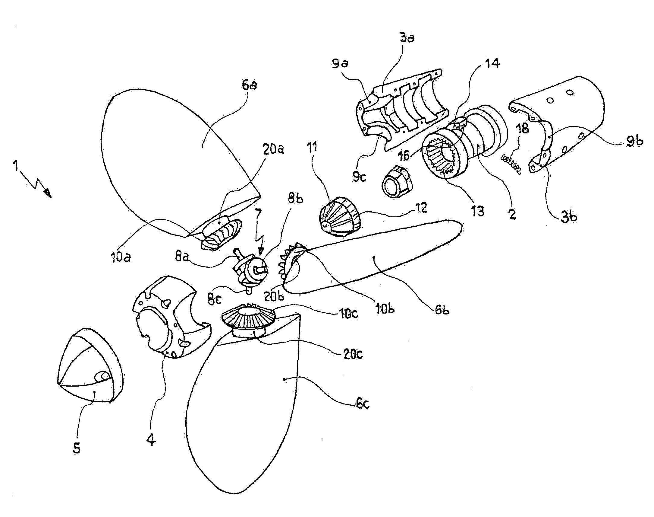
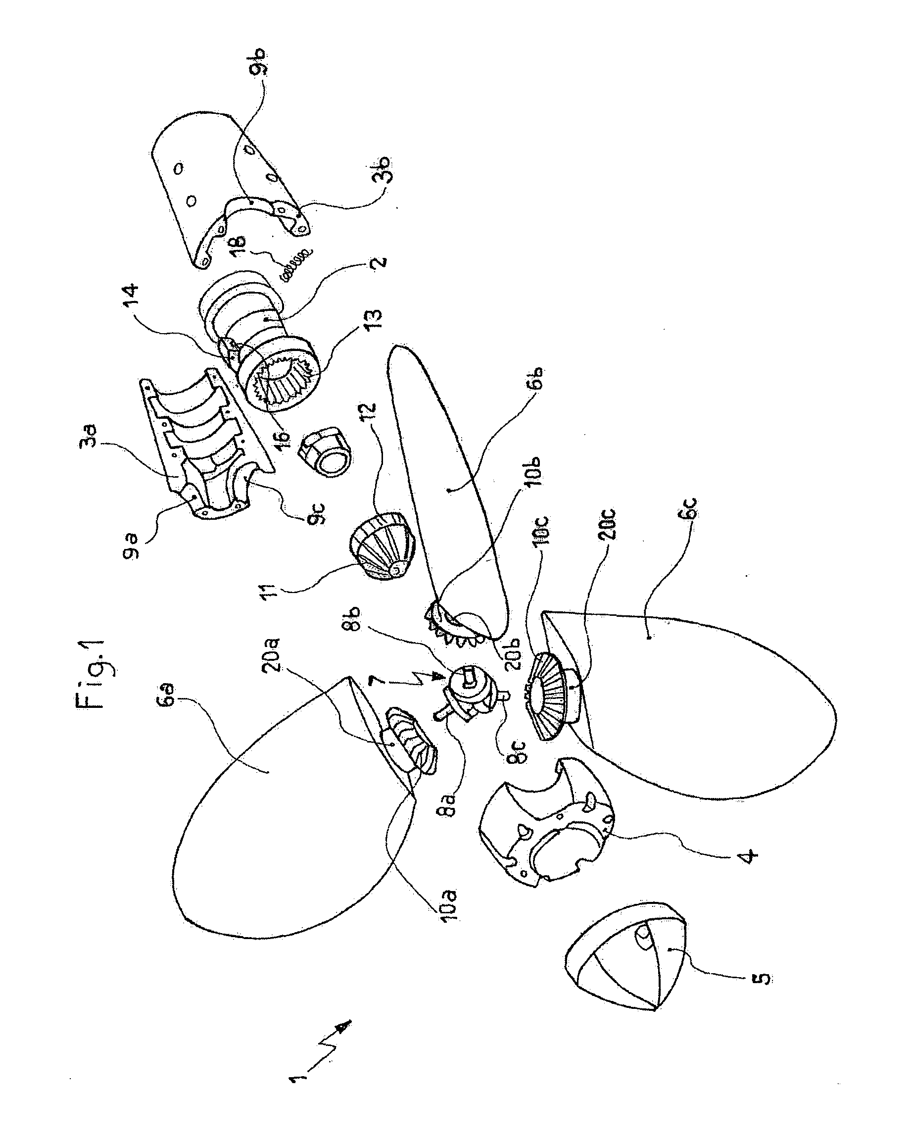
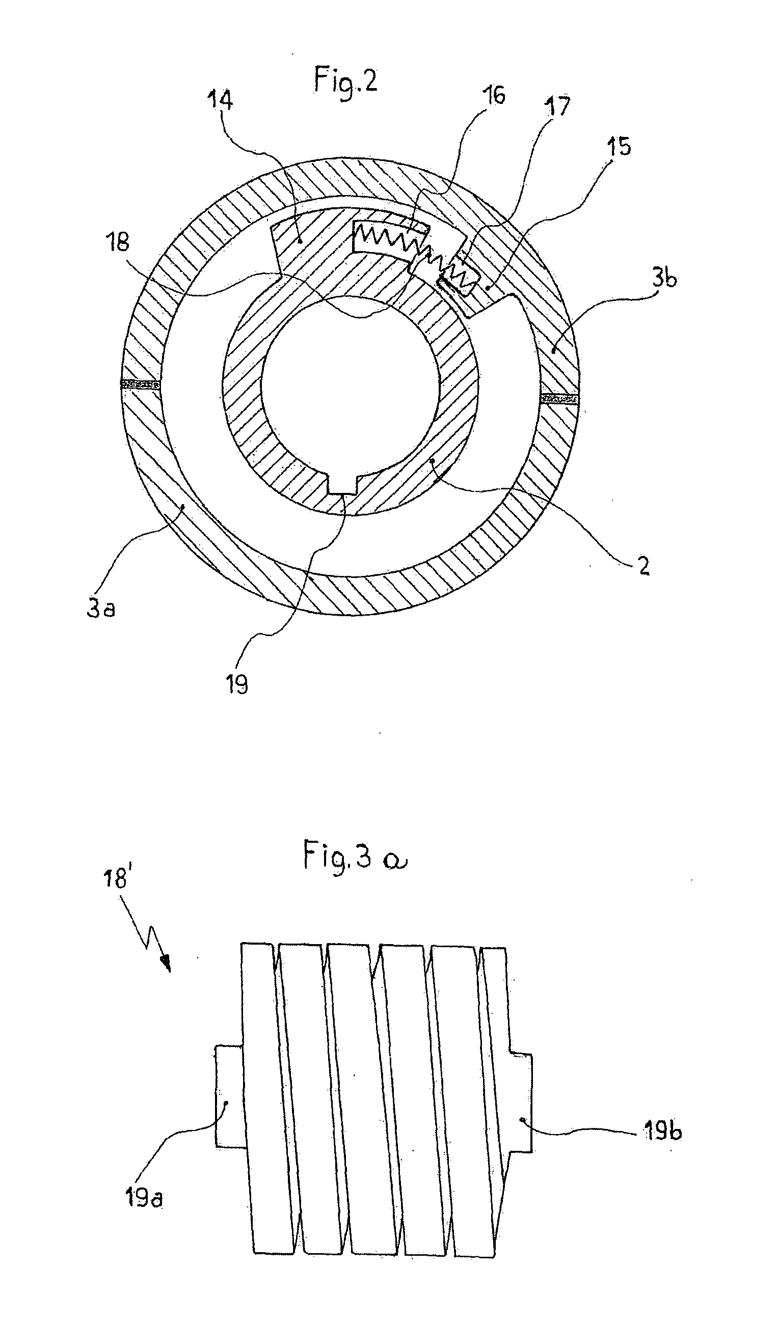
[0037]Referring to FIGS. 1 and 2, is shown a propeller 1 of the variable-pitch type, able to arrange in a feathered position, preferably for sailing boats. Such a propeller 1, according to a particular aspect of the present invention, is composed of, similarly to the propeller described in IT 1 052 022, a hollow cylindrical casing 3a, 3b, 4, divided in two semi-shell 3a, 3b interfixed by bolts (not shown), for example, and protected by a cylindrical end 4 lid, a tip 5, as well as a shaft (not shown), driven by an adapted engine and integral to a sleeve 2, that is coaxially coupled to the cylindrical casing 3, 3b, 4 itself, so as to allow, as later explained, the rotary motion transmission from the shaft to the cylindrical casing 3a, 3b, 4 itself.

[0038]Once assembled, the cylindrical casing 3a, 3b, 4 has circular openings 9a, 9b, 9c, in which pins 20a, 20b, 20c are rotatably housed, being integral at one of their ends to the corresponding blades 6a, 6b, 6c of the propeller 1, that ob...


PUM


Abstract

Variable-pitch propeller (1) of the type comprising at least one blade (6a, 6b, 6c) rotatably pivoted (20a, 20b, 20c) to a cylindrical casing of the propeller (3a, 3b, 4), a shaft coupled to an engine and coaxial to that propeller casing, a kinematic system (7, 8a, 8b, 8c, 10a, 10b, 10c, 11), coupled to the shaft, or to the propeller casing, and to above mentioned at least one blade, for regulating the rotary motion of said at least one blade around its own pivot axis to the propeller casing, as well as means (2, 14, 15) for transmitting the rotary motion of the shaft to the propeller casing, the propeller being shaped to provide at least one not null angular range for the free relative rotation of the above mentioned at least one blade (6a, 6b, 6c) around its pivot axis, relatively to the propeller casing (3a, 3b, 4). The propeller also comprises at least one elastic element (18, 18′) countering the relative rotation of said at least one blade relatively to the propeller casing (3a, 3b, 4), or vice versa.

Description

FIELD OF THE INVENTION[0001]The present invention refers to a propeller, preferably, but not exclusively, for marine use, of the so called variable-pitch type, wherein namely the fluid dynamic pitch of the blades might be changed while operating, thereby rendering extremely efficient the propeller itself upon the conditions wherein the latter is operating would change.BACKGROUND ART[0002]Variable-pitch propellers are particularly known, wherein the pitch is given automatically by activating the propeller itself, comprising a cylindrical propeller casing, on which the propeller blades are pivoted according to a cross direction relatively to the propeller casing axis itself, a shaft, that is coupled coaxially to the propeller casing, means for transmitting the rotary movement from the shaft to the propeller casing, as well as a kinematic system for regulating the rotary motion of each blade around its own pivot axis to the propeller casing, preferably adapted to transform the rotary m...

Claims


Application Information

Patent Timeline
Patent Type & Authority Applications(United States)
IPC IPC(8): F04D29/26
CPCB63H3/02B63H3/008
Inventor BIANCHI, MASSIMILIANO
Owner MAX PROP
Why Eureka
Try Eureka