
Method for converting biomass into synthesis gas using a pressurized multi-stage progressively expanding fluidized bed gasifier followed by an oxyblown autothermal reformer to reduce methane and tars

a technology of synthesis gas and fluidized bed, which is applied in the direction of combustible gas purification/modification, gasifier mechanical details, furnaces, etc., can solve the problems of significant inefficiencies and failure to meet the desired objectives of shoehorning existing gasifiers

Inactive Publication Date: 2010-02-18
SYNT
View PDF29 Cites 148 Cited by
  • Summary
  • Abstract
  • Description
  • Claims
  • Application Information

AI Technical Summary

Benefits of technology

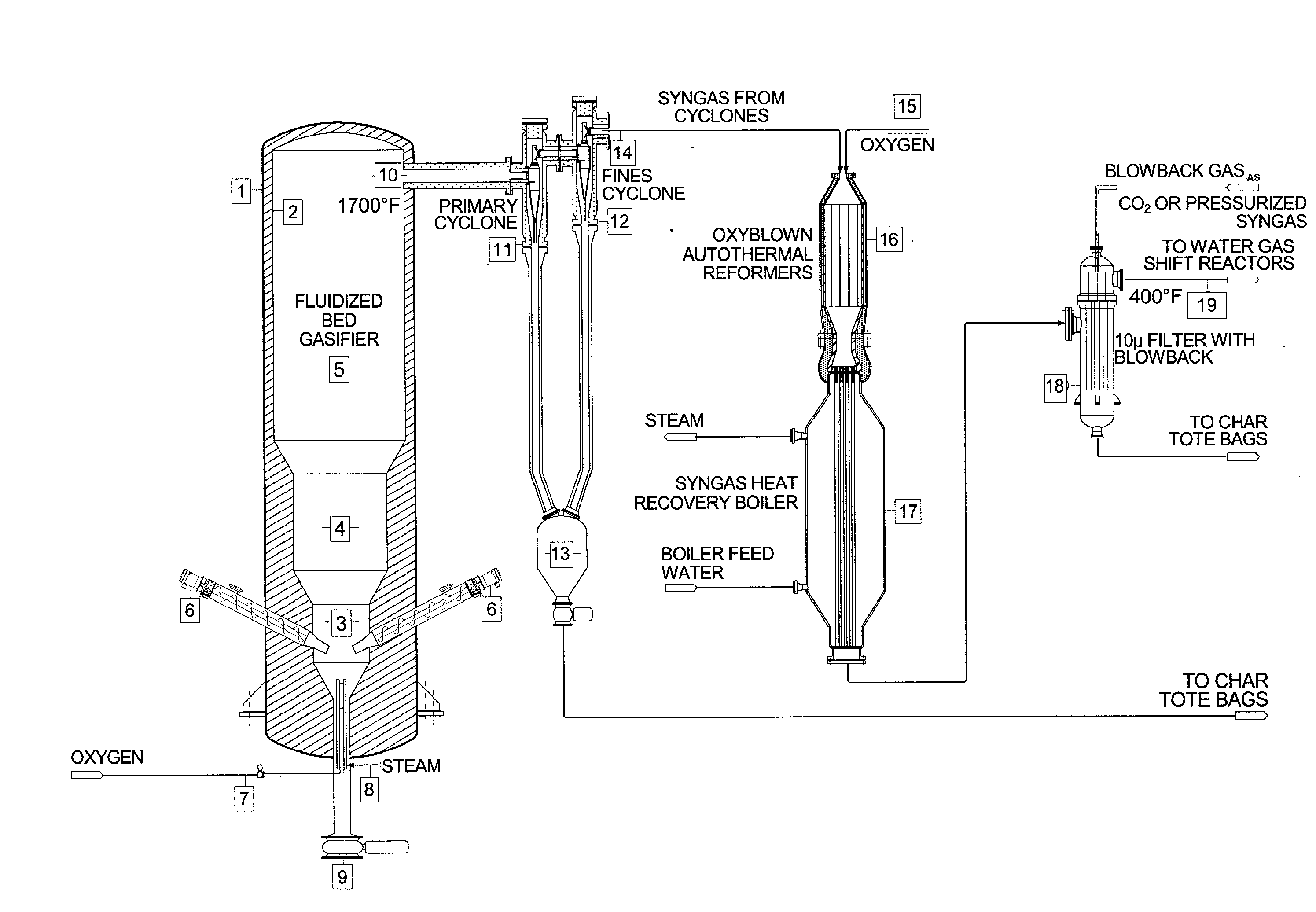
[0046]The biomass may be injected deep into the lowest section of the fluidized bed gasifier, thus ensuring that most of the methane, tars and other volatile components that are generated are converted into their various equilibrium components.
[0013]Finally, this invention may offer a significant benefit in terms of carbon management and sequestration. The gasifier may be deliberately operated in a substoichiometeric mode that can leave 2-10% of the biomass feedstock in the form of a highly valuable biochar and inorganic mineral ash mixture, which when recovered, can be sold and recycled as a premium fertilizer and soil enhancement agent.

Problems solved by technology

A limited amount of biomass conversion is being done with oxyblown gasifiers to make a synthesis gas (syngas) fuel for turbines.
In these cases, methane may be a co-product of lesser abundance, and in some cases may generate significant inefficiencies in the chemical conversion process.
Attempts at shoehorning existing gasifiers may not meet the desired objectives.

Method used


Image

  • Method for converting biomass into synthesis gas using a pressurized multi-stage progressively expanding fluidized bed gasifier followed by an oxyblown autothermal reformer to reduce methane and tars
  • Method for converting biomass into synthesis gas using a pressurized multi-stage progressively expanding fluidized bed gasifier followed by an oxyblown autothermal reformer to reduce methane and tars
  • Method for converting biomass into synthesis gas using a pressurized multi-stage progressively expanding fluidized bed gasifier followed by an oxyblown autothermal reformer to reduce methane and tars

Examples


Embodiment Construction

[0029]While preferable embodiments of the invention have been shown and described herein, it will be obvious to those skilled in the art that such embodiments are provided by way of example only. Numerous variations, changes, and substitutions will now occur to those skilled in the art without departing from the invention. It should be understood that various alternatives to the embodiments of the invention described herein may be employed in practicing the invention.

[0030]The invention provides systems and methods for converting biomass into syngas using a pressurized multi-stage progressively expanding fluidized bed gasifier to eliminate, minimize or reduce the formation of methane, volatiles and tars. The fluidized bed may contain a fluidizing medium that may range from sand to olivine particles. Olivine has the additional benefit of being able to convert a significant amount of tars into syngas.

[0031]This invention also discloses the use of an oxyblown autothermal reformer downs...


PUM


Abstract

The invention provides systems and methods for converting biomass into syngas using a pressurized multi-stage progressively expanding fluidized bed gasifier to eliminate or reduce the formation of methane, volatiles such as BTX, and tars. The gasifier may include a reactive stage that may receive a biomass feed through a feed line and oxygen through an oxygen feed line. The gasifier may also include a fluidized bed section that may be configured to receive the reaction products from the first stage, mix them and perform fluidized bed activity. A gasifier may also have a disengagement section that may be configured to separate fluidized media and particulate matter from syngas product. A gasification system may also include oxyblown catalytic autothermal reactor and a cryogenic air separation unit.

Description

[0001]The application claims the benefit of U.S. Provisional Application No. 61 / 089,869, filed Aug. 18, 2008, and U.S. Provisional Application No. 61 / 170,494, filed Apr. 17, 2009, which are hereby incorporated herein by reference in their entirety.BACKGROUND OF THE INVENTION[0002]According to the United States Department of Energy (USDOE), this half-decade (2005-2010) will see continued growth in the gasification industry. Worldwide capacity by 2010 is projected to exceed 70,000 MWth of syngas output from 155 plants and 451 gasifiers. The USDOE study indicates that many of the gasification plants being planned will select high temperature, oxygen-blown, slagging entrained gasifiers—such as those supplied by Shell, GE Energy, ConocoPhillips, and others. By 2010, it is predicted that Shell gasifiers will account for 43% of the total world market, Sasol Lurgi will slip to a share of 27%, and GE Energy gasifiers will decline to 24% of the world market.[0003]In terms of a near future (20...

Claims


Application Information

Patent Timeline
IPC IPC(8): B01J8/18B01J8/20
CPCC01B3/025C10K3/04C01B2203/0244C01B2203/0288C01B2203/04C01B2203/068C01B2203/0894C10J3/482C10J3/523C10J2200/09C10J2300/0916C10J2300/0959C10J2300/0973C10J2300/1668C10J2300/1678C10J2300/1687C10J2300/1838C10J2300/1884C10J2300/1892C10K1/026C10K3/005C10K3/006C10K3/023C01B3/382Y02P20/145
Inventor RANDHAVA, SARABJIT S.KAO, RICHARD L.HARVEY, TODDRANDHAVA, AJAIB S.RANDHAVA, SURJIT S.
Owner SYNT
Learn More