Implant for Deploying Bone Graft Material and Methods Thereof

a bone graft and implant technology, applied in the field of implant devices carrying bone graft material, can solve the problems of vertebral disc bulging or herniation, impinging on the nerves of the spine, and the support surfaces of existing intervertebral implants are typically not exactly the same as the superior and inferior surfaces, or endplates, of adjacent vertebrae, so as to improve the fusion between vertebrae.

Inactive Publication Date: 2010-02-18
PIONEER SURGICAL TECH INC
View PDF13 Cites 33 Cited by
  • Summary
  • Abstract
  • Description
  • Claims
  • Application Information

AI Technical Summary

Benefits of technology

[0018]An implant that carries bone graft material therein is provided and is configured to extrude bone graft material out therefrom during implantation. More particularly, the preferred implant includes first and second implant extrusion members that are operable to shift relative to each other from a pre-implantation configuration to an implantation configuration during implantation of the implant into an intervertebral space. The shifting of the extrusion members to the implantation configuration causes bone graft material in a cavity of the implant to be extruded out therefrom into the areas between upper and lower surfaces of the implant and corresponding facing surfaces of adjacent upper and lower vertebrae. In this manner, the bone graft material is immediately subjected to stress and loading after implantation. It is believed that such immediate exposure will beneficially improve the fusion between the vertebrae.

Problems solved by technology

Typically, damage to the spine can cause the vertebral discs to bulge or herniate, which can in turn impinge on the nerves of the spine.
As a result, the upper and lower support surfaces of existing intervertebral implants typically do not exactly match the contour of the superior and inferior surfaces, or endplates, of the adjacent vertebrae.
In addition, even with implants configured to generally conform to the surfaces of the vertebral end plates, the lack of uniformity of the surfaces of vertebral end plates from vertebrae to vertebrae and patient to patient can result in gaps between the endplates and the vertebral engaging surfaces of the implant.
However, in the presence of higher stress loading the implant provides higher resistance levels to implant compression so that the higher loading on the implant only creates small additional strain on the graft material.
However, it is believed that precision control over the stress to which the bone graft material will be exposed will be difficult if not impossible to achieve as this will largely depend on specifics unique to each patient.
With the slots filled with bone graft material, they will not provide the anticipated compression levels, and with the bone graft material in the slots or escaping out therefrom, the bone graft material may not be at the interface between the vertebrae and the implant.
According to Richelsoph, this gradual reduction in height results in increased loading being applied to the bone graft material and newly formed bone growth.
However, as stated above, is believed that precision control over the stress to which the bone graft material will be exposed will be difficult if not impossible to achieve as this will largely depend on specifics unique to each patient.

Method used


Image

  • Implant for Deploying Bone Graft Material and Methods Thereof
  • Implant for Deploying Bone Graft Material and Methods Thereof
  • Implant for Deploying Bone Graft Material and Methods Thereof

Examples


first embodiment

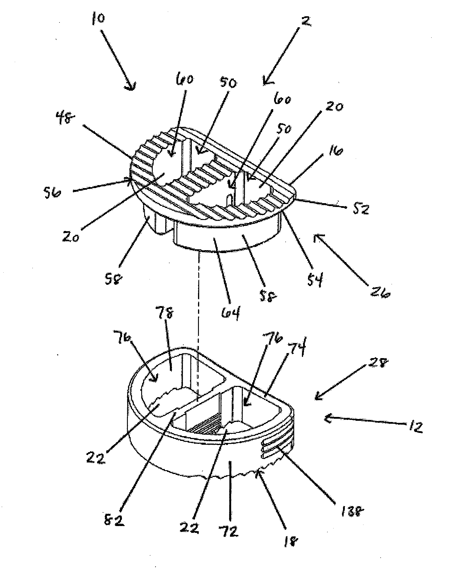
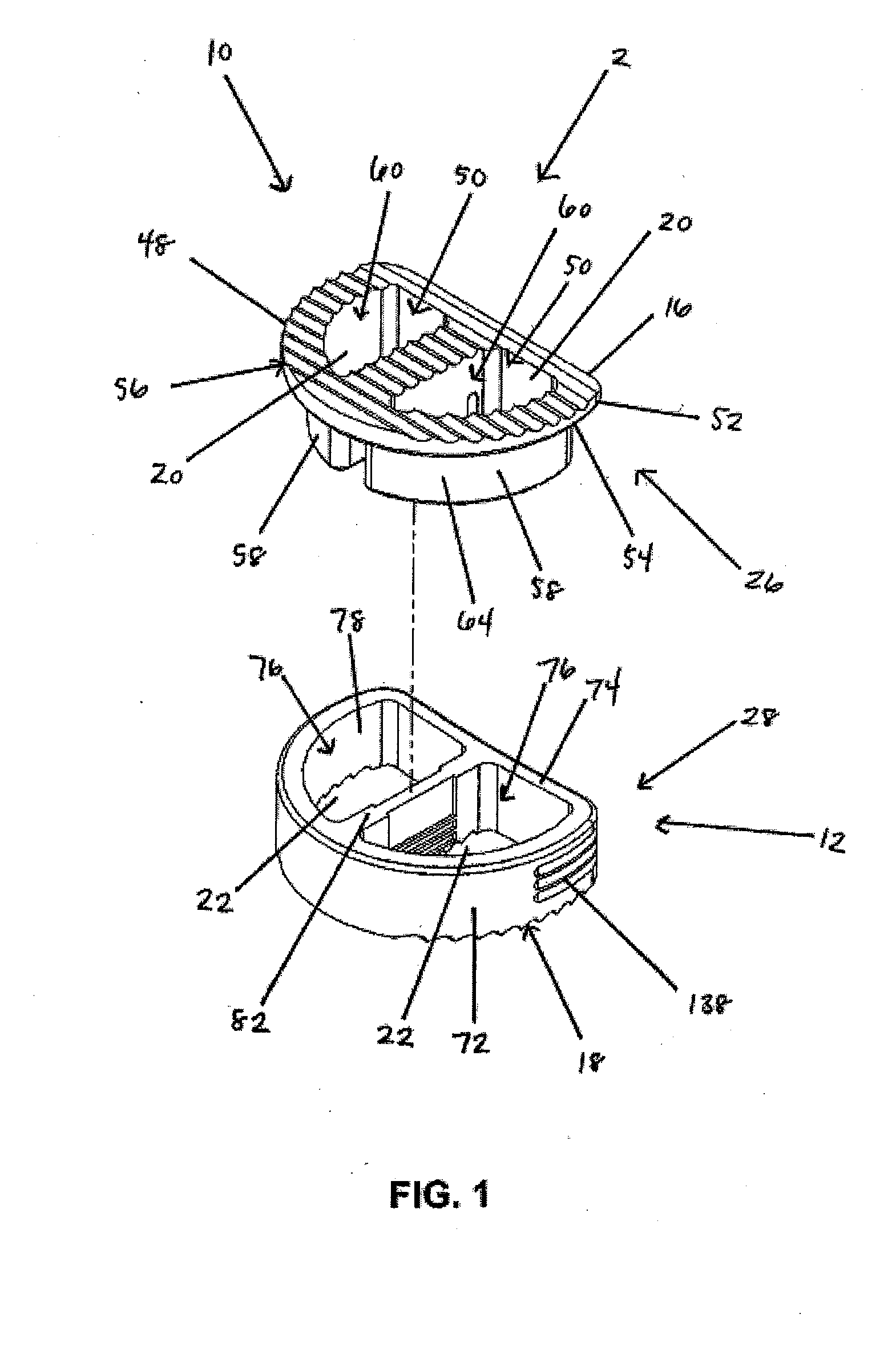
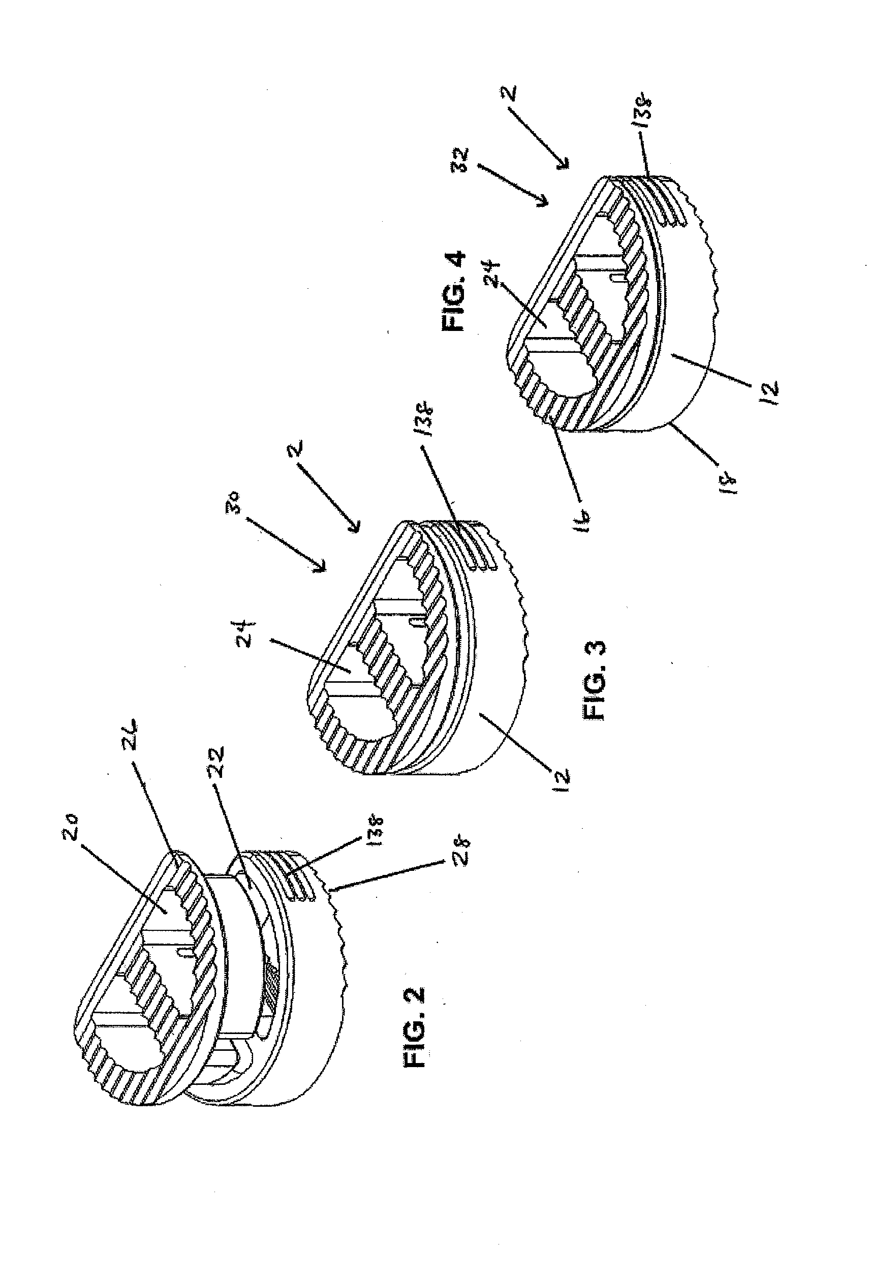
[0125]In a first embodiment, as shown in FIGS. 1-19, the implant 2 includes a first implant extrusion member 26 and a second implant extrusion member 28. The first implant extrusion member 26 includes an upper portion 48 for engaging a vertebral body. The upper portion includes an upper vertebral engaging surface 16 for engaging a facing vertebral body 6, an opening 50 of the upper surface 16 and an annular outer edge 52. Further, the upper portion 48 includes a lower surface 54 for engaging the second implant extrusion member. In addition, the first implant extrusion member 26 includes a depending wall portion 58 extending about a first cavity portion 60. The depending portion 58 is offset from the outer edge 52 of the upper portion 48 and extends from the opening 50 of the upper portion 48 downwardly a predetermined distance 62. As shown in FIG. 1, the depending portion 58 includes a generally continuous arcuate wall portion 64 extending around the first cavity portion 60. The cav...

third embodiment

[0142]In a third embodiment, such as shown in FIGS. 39-58, the first implant extrusion member 146 includes an arcuate wall 154 extending about a cavity 152. The wall 154 further includes upper and lower vertebral engagement surfaces 148 and 150 for engaging adjacent vertebrae 6 and 8. The wall 154 of the first implant extrusion member 146 further includes a throughbore 156 for receiving the second implant extrusion member 158 therein and allowing the second implant extrusion member 158 to shift therethrough to the implantation configuration 32.

[0143]To ease insertion of the second implant extrusion member 158 into the cavity 152 and through the bone graft material 34, the distal end 160 thereof can be tapered, such as with a conical distal end configuration 162 as shown in FIG. 39.

[0144]The pre-implantation configuration 30 of the first and second implant extrusion members 146 and 158 can be defined by the second implant extrusion member 158 being at any location other than that def...

fourth embodiment

[0152]In a fourth embodiment, as shown in FIGS. 59-75, the first and second implant extrusion members 194 and 196 have a ratchet connection 198 and are configured to be shifted laterally along the ratchet connection 198 relative to one another between adjacent vertebrae 6 and 8 from the pre-implantation configuration 30 to the implantation configuration 32. As shown in FIGS. 59 and 60, the first implant extrusion member 194 includes an arcuate wall 202 having opposite ends 200 thereof. The arcuate wall portion 202 includes a first upper vertebral engaging surface 204 and a first lower vertebral engaging surface 206 for engaging the faces of adjacent vertebral bodies 6 and 8.

[0153]Further, the end portions 200 of the first implant extrusion member 194 include pawl portions 208 extending therefrom. The pawl portions 208 include a wall portion 210, with the lower surface 212 of the pawl wall portion 210 positioned above the first lower vertebral engaging surface 206 and the pawl wall u...


PUM

PropertyMeasurementUnit
sizeaaaaaaaaaa
areaaaaaaaaaaa
viscositiesaaaaaaaaaa

Abstract

Invertebral implants are provided for carrying bone graft material and extruding the bone graft material between the implant and the adjacent vertebral bodies. The implants include first and second implant extrusion members shiftable relative to one another between a pre-implantation configuration having an enlarged cavity for receiving bone graft material therein and an implantation configuration having a smaller cavity. As the first and second implant extrusion members shift during implantation to the implantation configuration bone graft material is extruded from the cavity and into gaps or spaces between the upper and lower vertebral engaging surfaces of the implant and the adjacent vertebral bodies. After extrusion the bone graft material is subjected to spinal loading and stress to encourage strong bone growth therethrough.

Description

CROSS REFERENCE TO RELATED APPLICATIONS[0001]This application claims the benefit of the filing date of U.S. Provisional Application 61 / 089,138, filed Aug. 15, 2008, which is hereby incorporated in its entirety herein.FIELD OF THE INVENTION[0002]The invention relates to implant devices carrying bone graft material for implantation within an intervertebral space for immobilization and fusion of adjacent vertebrae.BACKGROUND OF THE INVENTION[0003]Back pain can develop due to traumatic injury to the spine, disease, or genetic defect. Typically, damage to the spine can cause the vertebral discs to bulge or herniate, which can in turn impinge on the nerves of the spine. One method of treating a damaged disc is by immobilizing the area around the injured portion and fusing the immobilized portion by promoting bone growth between the immobilized spine portions. This often requires implantation of an intervertebral device to provide the desired spacing between adjacent vertebrae.[0004]Typica...

Claims


Application Information

Patent Timeline
Patent Type & Authority Applications(United States)
IPC IPC(8): A61F2/44
CPCA61F2/30744A61F2310/00023A61F2/4601A61F2/4611A61F2002/30062A61F2002/3008A61F2002/30331A61F2002/305A61F2002/30507A61F2002/30522A61F2002/30551A61F2002/30563A61F2002/30571A61F2002/30579A61F2002/30594A61F2002/30601A61F2002/30604A61F2002/30787A61F2002/30904A61F2002/4475A61F2002/4629A61F2210/0004A61F2220/0025A61F2220/0033A61F2250/0098A61F2310/00017A61F2/446A61F2002/3055A61F2002/30593
Inventor KILPELA, THOMAS S.HOFFMAN, JEFFREY A.JANOWSKI, BRIAN P.
Owner PIONEER SURGICAL TECH INC
Why Eureka
Try Eureka