Steel-frame building and method of making

a technology of steel frame and building, applied in the field of steel frame building and making method, can solve the problems of both steel quantity and fabrication cost being higher than needed for buildings constructed with the current joint connection technology, and achieve the effects of reducing construction costs, reducing construction costs, and reducing construction costs

Active Publication Date: 2010-02-25
MITEK HLDG INC
View PDF23 Cites 17 Cited by
  • Summary
  • Abstract
  • Description
  • Claims
  • Application Information

AI Technical Summary

Benefits of technology

[0019]In the present invention, as stated above, the gusset plates cover and protect the beam-to-column joint connections which attach one or two or more beams to a column. The columns typically utilize the gusset plates connection taught in U.S. Pat. No. 5,660,017, in which the gusset plates are not only welded to the beams (or cover plates on the beams, as the case may be), but, the gusset plates are also, welded directly, in a vertical direction, to the flange tips of the column by fillet welds, thus, creating through the gusset plates substantial moment-resisting connections. In other cases, where the retrofit of existing prior conventional joint connections is desired, as taught in U.S. Pat. No. 7,178,296, the continuous gusset plates may not be welded at all to the column that they sandwich, preferring instead to provide a beam-to-beam connection that is structurally independent of the column and which connection can mitigate the damage caused by the sudden, violent loss of support from that column or violent loss of joint connections of the beams to the column.
[0020]It is therefore an object of this invention to provide an improved, continuous, beam-to-beam connection across a column, which connection can mitigate the damage caused by the sudden, violent loss of support from that column; or can mitigate the damage caused by the sudden, violent loss of joint connections o

Problems solved by technology

Further, because steel frame structures constructed with current joint connection technology utilizes too much steel, they are stiffer than needed by design.
As a result, both steel quantities and fabrication costs are higher than need be for buildings constructed with the current joint connection technology, while not optimizing the behavior characteristics of the gusset pl

Method used


Image

  • Steel-frame building and method of making
  • Steel-frame building and method of making
  • Steel-frame building and method of making

Examples


Embodiment Construction

[0039]The structural steel commonly used in the steel frameworks of buildings is generally produced in conformance with standards A-36, A-572 and A-992 specifications. High strength aluminum and other high-strength metals might be found suitable for use in this invention under some circumstances. It is recognized that other materials, particularly in the gusset plates and, possibly in other elements of the joint connections, might be used. For example, in the gusset plates, other shapes might be used in addition to those illustrated herein. So, the invention is not limited to the precise details of the embodiments shown and described herein.

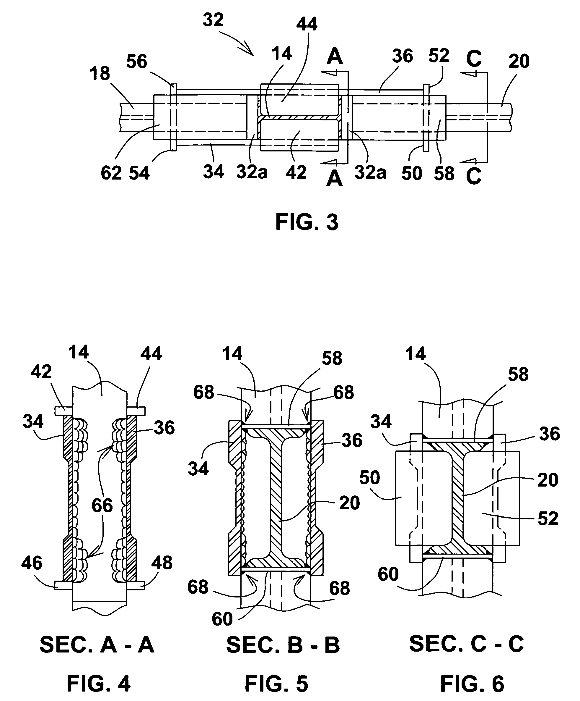
[0040]Commonly shown in the drawings herein are fillet welds, and full-penetration, single bevel groove welds. The mention or illustration of a particular kind of weld herein, does not preclude the possibility of other kinds of welds being found suitable by a person skilled in the art. In a particular application, it might well be found suitable ...


PUM


Abstract

An improved building structure and method for making steel frame buildings includes a beam-to-column or beams-to-column joint or connection which is most preferably shop fabricated (as opposed to on-site fabrication) and which offers a considerable savings in both steel requirements (i.e., material savings) and labor to make the joint connection. Also, because material utilization is improved in the connection, the new structure is more resistant to damage by seismic events (i.e., earthquake), by severe weather, and to damage from blast effects (i.e., terrorist attack or accident), than was the prior technology. The improved building structure also mitigates against progressive collapse of the building.

Description

CROSS REFERENCE TO RELATED APPLICATION [0001]This application is related to U.S. application Ser. No. 08 / 354,954, filed 13 Dec. 1994, now U.S. Pat. No. 5,660,017, granted 26 Aug. 1997.BACKGROUND OF THE INVENTION[0002]Buildings, towers and similarly heavy structures commonly are built on and around a steel framework. A primary element of the steel framework is the joint connection of the beams to the column. An improved structural joint connection is disclosed in U.S. Pat. No. 5,660,017. However, advanced stress analysis techniques and study of building collapse mechanisms following seismic and blast events (i.e., terrorist bombings) has resulted in the present improvement invention.[0003]Briefly, the current technology teaches a joint structure for joining one or more beams in a supporting relationship to a column, including a pair of gusset plates spaced apart and sandwiching between them a column and a connecting beam or beams, with the gusset plates extending outwardly from the c...

Claims


Application Information

Patent Timeline
IPC IPC(8): E04B1/24E04B1/19E04B1/98E04H9/02E04B1/38
CPCE04B1/2403E04B2001/2415E04H9/14E04B2001/2496E04H9/02E04B2001/2448Y02A50/00E04H9/0237E04B1/24
Inventor KARNS, JESSE E.
Owner MITEK HLDG INC
Why Eureka
Try Eureka