Fuel pump

a technology of fuel pump and fuel tank, which is applied in the direction of liquid fuel engine, combustion air/fuel air treatment, positive displacement liquid engine, etc., can solve the problems of fuel leakage in the resulting space, shortening the life and effectiveness of the engine, and pressure spikes, etc., to facilitate reciprocating movement

Active Publication Date: 2010-02-25
CUMMINS INC
View PDF37 Cites 24 Cited by
  • Summary
  • Abstract
  • Description
  • Claims
  • Application Information

AI Technical Summary

Benefits of technology

[0006]The present invention has been developed to address the above and other problems in the related art. According to some embodiments of the present invention, a fuel pump is provided that comprises a fuel pump barrel including a bore having first and second ends separated by a length of bore, the second bore end forming an opening. The fuel pump barrel also includes an annular drain groove within the bore, spanning the bore's circumference, and a drain duct that is fluidically coupled to the drain groove. A plunger is provided that has an outer diameter that is slightly less than the bore diameter, forming a clearance that facilitates reciprocating movement within the bore. The plunger is positioned in the bore and extends through the bore opening to form a pumping chamber. An annular seal is provided that is positioned adjacent to the drain groove and located substantially at the second end of said bore. A seal support aids to retain the seal in position.

Problems solved by technology

Because the plunger diameter must necessarily be less than the bore diameter, fuel leakage in the resulting space can occur.
Such fuel leakage contaminates the engine lube oil and causes a reduction in the oil's viscosity, thus shortening its life and effectiveness.
However, this approach has the disadvantage of pressure spikes occurring due to dilation of the plunger under axial load.
Such pressure spikes hinder the operation of the seal.

Method used


Image

  • Fuel pump
  • Fuel pump
  • Fuel pump

Examples


Embodiment Construction

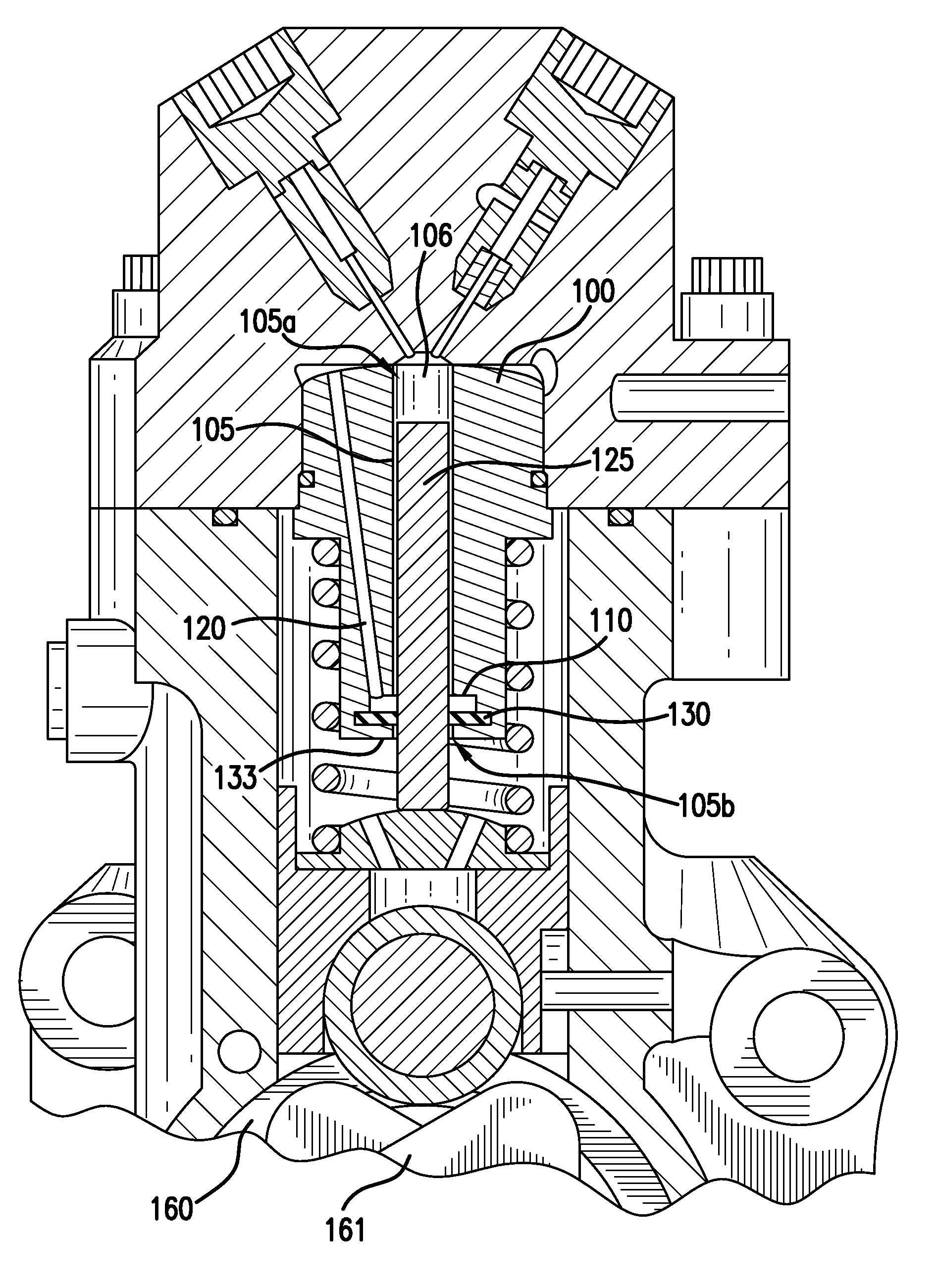
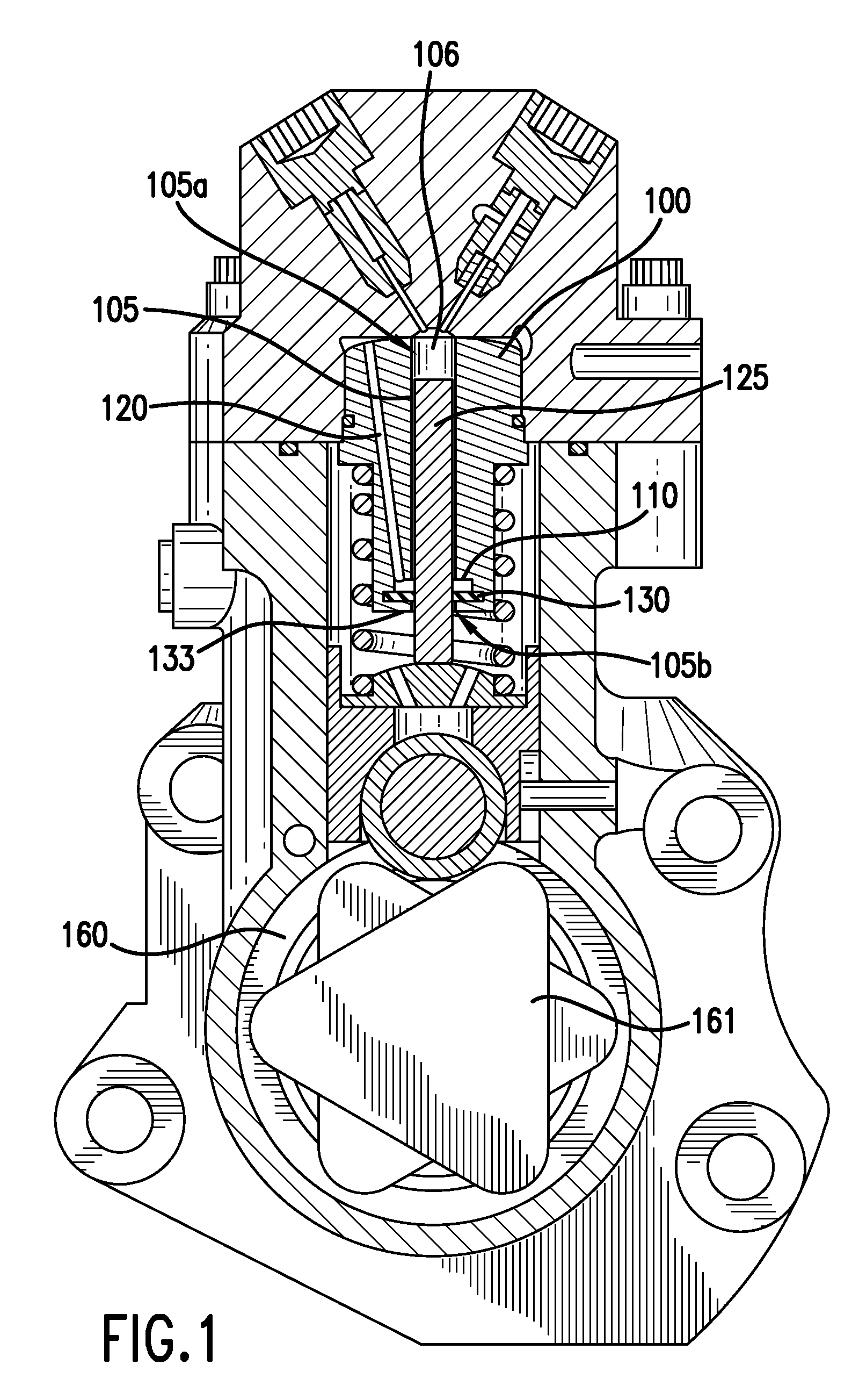
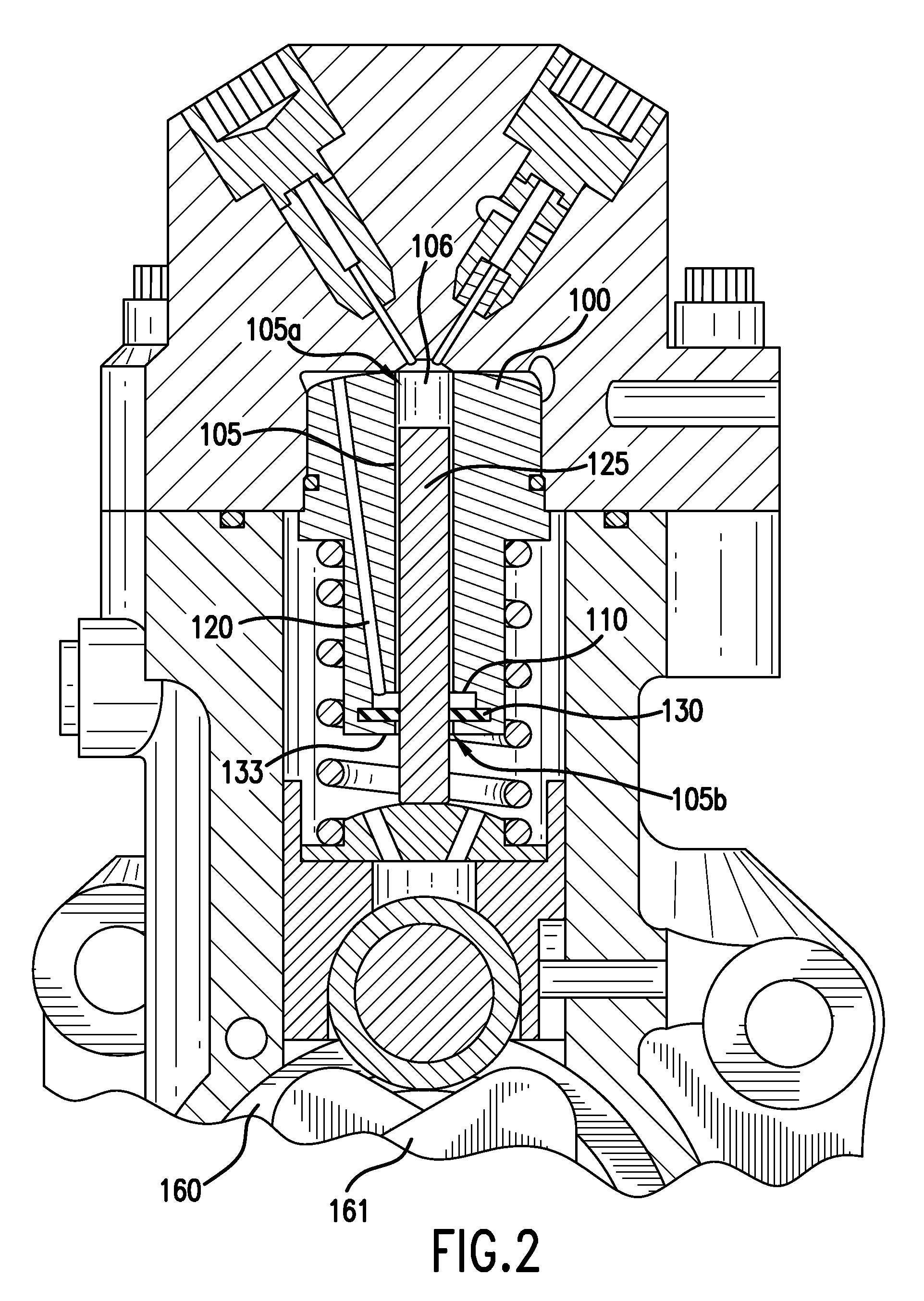
[0014]Exemplary embodiments of the present invention will now be described more fully with reference to the accompanying drawings. The matters exemplified in this description are provided to assist in a comprehensive understanding of various embodiments of the present invention disclosed with reference to the accompanying figures. Accordingly, those of ordinary skill in the art will recognize that various changes and modifications of the embodiments described herein can be made without departing from the scope and spirit of the claimed invention. Descriptions of well-known functions and constructions are omitted for clarity and conciseness. To aid in clarity of description, the terms “upper,”“lower,”“above,”“below,”“left” and “right,” as used herein, provide reference with respect to orientation of the accompanying drawings and are not meant to be limiting. The term “substantially” as used herein may be applied to modify any quantitative representation which could permissibly vary w...


PUM


Abstract

A fuel pump is disclosed wherein a substantially cylindrical plunger bore is provided with an annular drain groove fluidically coupled to a drain duct. A pump plunger is driven by a drive system located in a separate mechanical compartment that holds a reservoir of lubricating oil. An annular seal is provided adjacent the drain groove substantially at the end of the bore and retained in position by a seal support. Exemplary embodiments provide the drain groove and seal as being positioned immediately adjacent one another so that the seal forms a lower wall of the drain groove.

Description

BACKGROUND[0001]1. Field of the Invention[0002]The present invention relates to fuel pumps for supplying fuel to internal combustion engines. More particularly, the present invention relates to a fuel pump having a plunger bore and seal configured to facilitate an increase in the pressurized region along the length of the pump plunger bore.[0003]2. Description of the Related Art[0004]Today's engine designers must meet the challenge of government mandated emissions criteria while striving to improve engine fuel efficiency. In rising to this challenge, designers create fuel systems that operate at higher pressures than systems of the past. In so doing, greater performance demands are placed on fuel pump components and operations. Fuel pumps typically include a pump plunger positioned in the bore of a fuel pump barrel and sized so as to permit reciprocating motion within the bore. Pump plungers are driven by a drive system positioned in a separate mechanical compartment supplied with l...

Claims


Application Information

Patent Timeline
Patent Type & Authority Applications(United States)
IPC IPC(8): F02M31/20F04B53/04F02M37/04
CPCF02M59/102F04B1/0408F04B53/14F04B1/0448F02M59/442F04B1/0421F04B53/143F02M37/043F04B15/02F04B19/22F04B53/04F04B53/08F04B53/10F04B53/162F04B53/18
Inventor CROFTS, JOHN D.SIMMONS, SCOTTTHAYER, WESLEY R.DOSZPOLY, BELARIX, DAVE M.SHAULL, ANTHONY A.BUCHANAN, DAVID L.
Owner CUMMINS INC
Why Eureka
Try Eureka