Internal combustion engine with actuating oscillating cylinders

a technology of oscillating cylinders and internal combustion engines, which is applied in the direction of internal combustion piston engines, combustion engines, machines/engines, etc., can solve the problems of reducing engine efficiency, -stroke engines, and generally not as efficient two-stroke engines, so as to facilitate reciprocation of pistons, enhance efficiency, and accelerate exhaust exchange

Inactive Publication Date: 2006-08-17
SPRINGER
View PDF11 Cites 5 Cited by
  • Summary
  • Abstract
  • Description
  • Claims
  • Application Information

AI Technical Summary

Benefits of technology

[0019] Another advantageous feature of the present invention is that the combustion piston is topped with a cap that is preferably domed in such a configuration to enhance a swirl of charge flow. By introducing the air and fuel into the combustion chamber just above the combustion piston cap, a swirl of the introduced fluid will result, enhancing the even distribution of the air and fuel and increasing the burn efficiency. The combustion piston cap comprises a delivery cavity through which the charge is delivered to the combustion chamber. The delivery cavity has an entry port into which charge enters from the pumper chamber and an exit port through which the charge enters the combustion chamber. During the combustion cycle, it is possible that combustion exhaust may enter the delivery cavity. The present invention is configured so that the entry port of the delivery cavity aligns with the blower outlet once each cycle to blow out any residual exhaust in the delivery cavity. One advantage of the present invention is that it provides an effective vehicle for vaporizing the fuel, enhancing the mixture of fuel and air, prior to injection into the combustion chamber. By doing so, it may be possible to decrease the amount of fuel delivered to obtain the same power.
[0020] In the present embodiment, the pumper piston and the combustion piston are positioned with respect to the crank shaft so as to move synchronously in cycle so that both pistons reach apex simultaneously. It is contemplated that a variation in the configuration of the present invention would permit asynchronous movement within respective cylinders and still work effectively.
[0021] It is contemplated that an optional feature may be provided to facilitate reciprocation of the piston in the combustion and pumper chamber. Specifically, in one embodiment, at least one roller is provided on each side of the piston rod that rides axially within the chamber in a groove in the side wall of the chamber. If desired, more than one roller on each side may be provided.
[0022] One advantageous feature of the present invention is a blower configured and positioned to purge the combustion chamber of exhaust, permitting a faster exchange of exhaust and refreshed charge. The blower is preferably powered by the crank shaft. Preferably, the blower is also powered during start up by an auxiliary motor that drives the blower initially to enhance its effectiveness in forcing exhaust out of the combustion chamber. Preferably, means for providing a misted supply of water to the blower line that draws heat from the engine will serve to crack some of the water to generate hydrogen from the water molecules. The hydrogen is then delivered as part of the blower supply to the combustion chamber to enhance combustion.
[0023] An optional feature of the present invention comprises a breakdown crank that facilitates the removal of the pumper chamber from the engine if so desired for replacement or repair. The breakdown crank comprises a segmented shaft having a first portion linked to the combustion piston rod and a second portion linked to the pumper piston rod. The first portion has a first end that abuts a first end of the second portion, each of which comprises an internal bore portion that join together to form a contiguous bore. A pin resides within the bore for purposes of aligning the first and second portions of the crank. At least one key is radially positioned within a keyway at the juncture of the first and second shaft portions to secure the pin within the bore and to ensure radial alignment. With this arrangement, if it is desired to detach the pumper side of the engine from the combustion side, the key or keys can be removed and the crank shaft portions detached.
[0024] The present invention further comprises a variable compression feature that permits a change in the volume of the combustion chamber that impacts the resulting power generated by combustion. In the preferred embodiment, the trunnion about which the combustion chamber oscillates sits within an eccentric ring that itself sits within an aperture in the wall. The eccentric ring is configured to rotate in a manner so that the axial position of the trunnion relative to the combustion wall moves so as to change the combustion chamber volume. Preferably, the trunnion moves relative to the chamber 62 / 1000 inches. If desired, the eccentric ring may be secured within an axial slot so that as the ring rotates, lateral movement does not occur.

Problems solved by technology

Two-stroke engines, however, are generally not as efficient as four-stroke engines because two-stroke engines do not effectively remove all of the exhaust gases from the combustion chamber before the next power producing cycle.
This is disadvantageous because some of the fresh air-fuel mixture escapes through the exhaust port reducing engine efficiency by failing to utilize all of the fresh air-fuel mixture during the combination process.
In addition, some of the exhaust gases mix with the incoming fresh air-fuel mixture which further reduces engine efficiency because noncombustible gases remain in the combustion chamber during the subsequent power cycle.
This approach leads to considerable complexity in crankcase design, requires additional working components, creates sealing and lubrication problems, and adds to the cost of manufacturing, operation and maintenance.
However, superchargers include serious disadvantages such as increased weight, added complexity, reliability handicaps, and maintenance problems.
Conventional internal combustion engines also lose power and efficiency because the reciprocating piston is attached to the crankshaft by a connecting rod and a wrist pin to translate linear reciprocating motion of the piston into rotational movement of the crankshaft.
The use of the connecting rod and wrist pin results in uneven and excessive wear to the piston and cylinder wall because lateral forces are transmitted through the connecting rod in directions other than through the centerline of the piston.
These passageways create a complicated system that is difficult to manufacture and expensive to assemble U.S. Pat. No. 1,135,365 issued to Dock and U.S. Pat. No. 1,877,760 issued to Berner disclose oscillating cylinder internal combustion engines where the rocking motion created by the oscillating cylinder requires a complex series of chambers, passageways and apertures to regulate the flow of the fuel mixture and exhaust gases through the engine.

Method used


Image

  • Internal combustion engine with actuating oscillating cylinders
  • Internal combustion engine with actuating oscillating cylinders
  • Internal combustion engine with actuating oscillating cylinders

Examples


Embodiment Construction

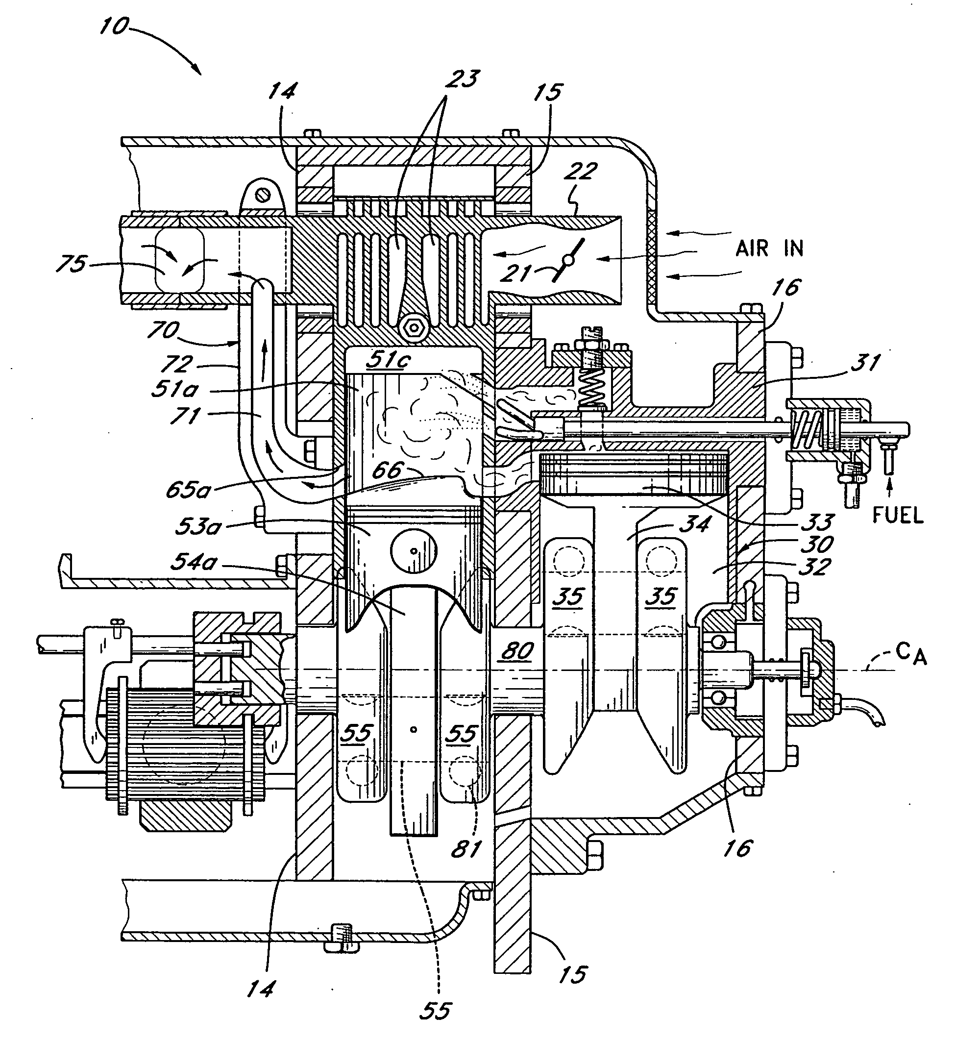
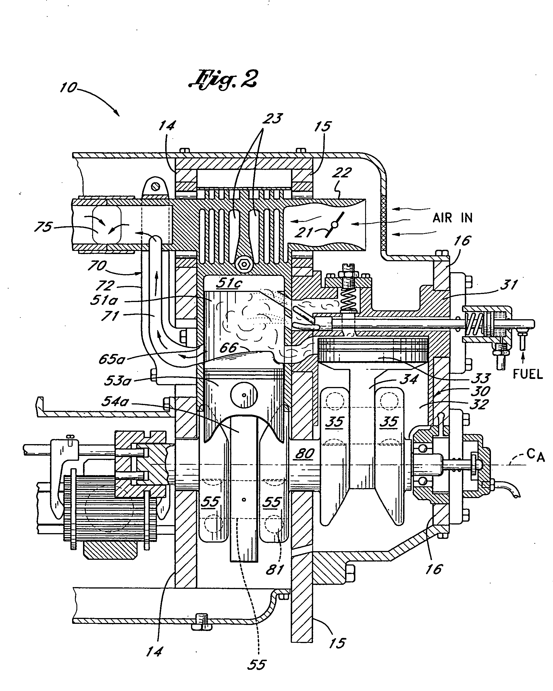
[0048] Reference is now made to the figures wherein like parts are designated with like numerals throughout. While the accompanying figures show the improved engine oriented vertically, i.e., the pistons moving up and down, it should be readily appreciated that the present invention may be oriented for operation in many directions. For purposes of describing and claiming the present invention on a mare general level, pistons will be described as moving inward and outward away from the head of a cylinder, rather than downward or upward, as specifically shown in the figures.

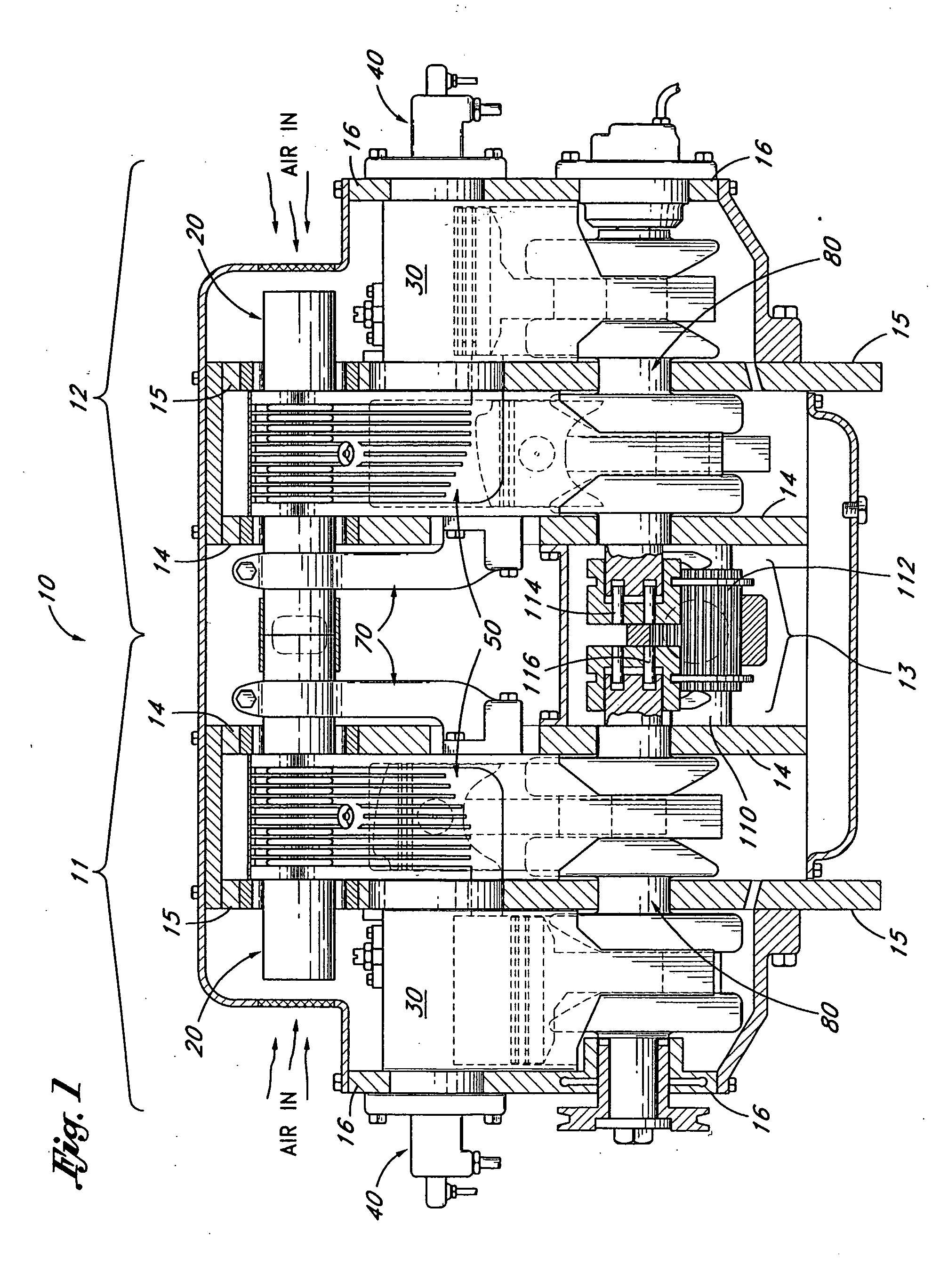
[0049] With reference to FIG. 1 and by way of broad introduction, the improved engine 10 comprises an air intake system 20 that draws fresh air into the engine 10. This air is first used to draw heat away from the combustion portion of the engine and then is delivered to an air cylinder 30 (or air cylinder, for short), for compression. The compressed air is, in part, mixed with fuel from a fuel delivery system 40 ...


PUM


Abstract

An internal combustion engine having one or more modules each employing fluidly-communicating, oscillating, power cylinder and air cylinder. The power and air cylinders oscillate about separate, individually supporting sets of trunnions positioned non-linearly with respect to each other and permitting the passage of air therethrough. The air cylinder includes a pre-combustion chamber for the purpose of withholding the delivery of a portion of compressed air to the power cylinder until all spent gases have been evacuated from the power cylinder. Means for enhancing fuel dispersion and / or vaporization is provided whereby cavities are provided in the cap of both the air cylinder and the power cylinder that are in selective synchronous fluid communication. A blower is provided to not only assist in the elimination of exhaust from the combustion chamber but also purge the combustion piston cap cavity of exhaust backflow prior to the delivery of fresh charge

Description

BACKGROUND OF THE INVENTION [0001] 1. Field of the Invention [0002] The present invention relates to internal combustion engines having one or more modules that employ pairs of fluidly communicating oscillating cylinders and, more particularly, to an oscillating cylinder engine that enhances fuel burning efficiency. [0003] 2. Description of the Related Art [0004] With conventional internal combustion engines, power is derived from the combustion of air and fuel (e.g., gasoline and air) resulting from the ignition of a highly compressed air-fuel mixture contained within one or more combustion chambers. In a typical internal combustion engine, the inward motion of a reciprocating piston within a cylinder compresses the air-fuel mixture for ignition and combustion. The expanding gases resulting from combustion impart a tremendous force against the piston and drive it outwardly within the cylinder. The piston is typically linked to a crankshaft in a manner such that linear reciprocating...

Claims


Application Information

Patent Timeline
Patent Type & Authority Applications(United States)
IPC IPC(8): F02B33/22F02B41/06F02B59/00
CPCF02B33/22F02B59/00
Inventor SPRINGER, JOSEPH E.
Owner SPRINGER
Why Eureka
Try Eureka