Fuel control system

a fuel control system and cold start technology, applied in the direction of electric control, combustion air/fuel air treatment, engine starters, etc., can solve the problems of increased noxious emissions from the engine, insufficient fuel vaporization, and high fuel consumption, so as to reduce the possibility of fuel condensation in the intake manifold, accelerate engine starting, and improve fuel vaporization

Inactive Publication Date: 2004-01-08
HITACHI LTD
View PDF25 Cites 4 Cited by
  • Summary
  • Abstract
  • Description
  • Claims
  • Application Information

AI Technical Summary

Benefits of technology

[0016] The outlet of the cold start fuel injector is fluidly connected to the interior chamber of the auxiliary intake manifold so that fuel from the cold start fuel injector, after vaporization by conventional heaters, passes through the control orifices to the combustion chambers for the engine. Furthermore, preferably the control orifice is positioned closely adjacent the intake valve for its associated combustion chamber so that, after the fuel vapor charge passes through the control orifice, the charge must pass through only a short length of the intake manifold. Consequently, the possibility of fuel condensation in the intake manifold is minimized. Additionally, the fuel charge from the auxiliary intake manifold reaches the internal combustion chambers during the initial cranking of the engine thus achieving quicker engine starting than previously known.
[0017] A shroud, which may be either at a fixed position or having a variable position under control of the ECU, is optionally associated with each control orifice. The shroud thus controls the introduction of the fuel charge from the auxiliary intake manifold into the airflow stream through the primary intake manifold to achieve better fuel vaporization, lower emissions and better engine starting.
[0018] Similarly, two or more control orifices may be associated with each combustion chamber. The use of two or more control orifices between the auxiliary manifold and the engine combustion chamber achieves additional swirling of the fuel charge from the auxiliary intake manifold. Such additional swirling enhances vaporization of any unvaporized fuel in the fuel stream. The control orifices may also be opened to achieve better fuel vaporization.

Problems solved by technology

During a cold start engine condition, however, insufficient fuel vaporization, at least where a liquid fuel such as gasoline or diesel fuel is used, occurs if the multi-point injectors are used to provide fuel to the engine.
The introduction of unvaporized or only partially vaporized fuel results in high fuel consumption, increased noxious emissions from the engine, as well as poor engine performance and slow starting.
However, since the air / fuel mixture from the cold start fuel injector must pass through the still cold primary intake manifold of the engine, fuel condensation can occur within the intake manifold during a cold engine condition.
Such fuel condensation adversely affects the efficiency of the engine and increases noxious emissions from the engine.
Furthermore, since the air / fuel mixture from the cold start fuel injector must travel entirely through the relatively large volume primary intake manifold before the air / fuel mixture reaches the internal combustion chambers, an appreciable time delay occurs between the activation of the cold start fuel injector and the time that the air / fuel mixture actually reaches the engine combustion chambers.
This time delay may extend for several revolutions of the engine main shaft thus resulting in excessive engine cranking as well as slow engine starting.

Method used


Image

  • Fuel control system
  • Fuel control system
  • Fuel control system

Examples


Embodiment Construction

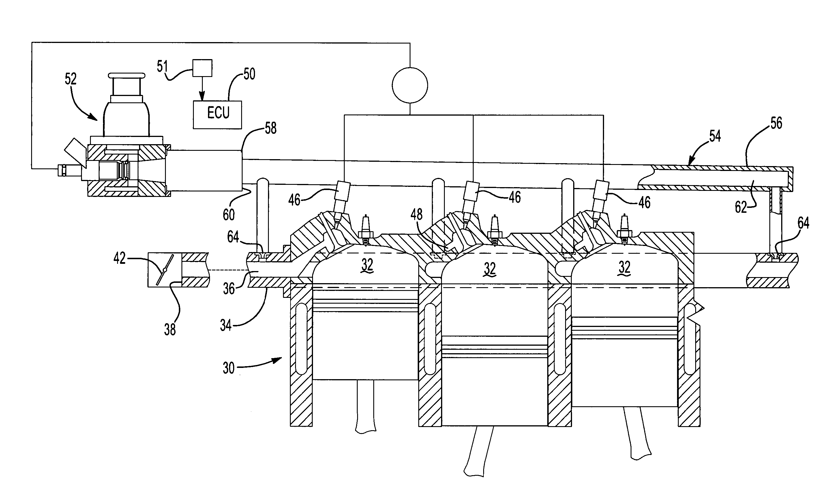
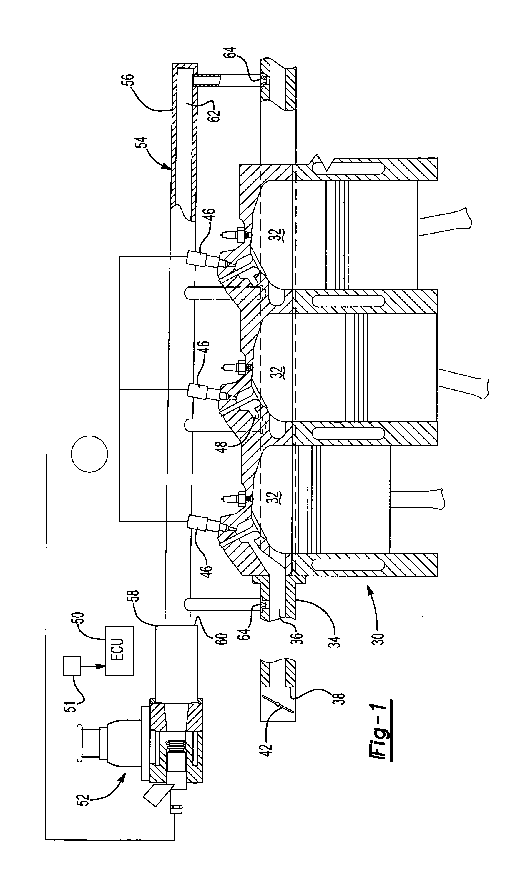
[0029] With reference first to FIGS. 1 and 2, an internal combustion engine 30 having a housing 31 is shown having several internal combustion chambers 32. These internal combustion chambers 32 are typically arranged in one or two banks of three or four internal combustion chambers 32 per bank.

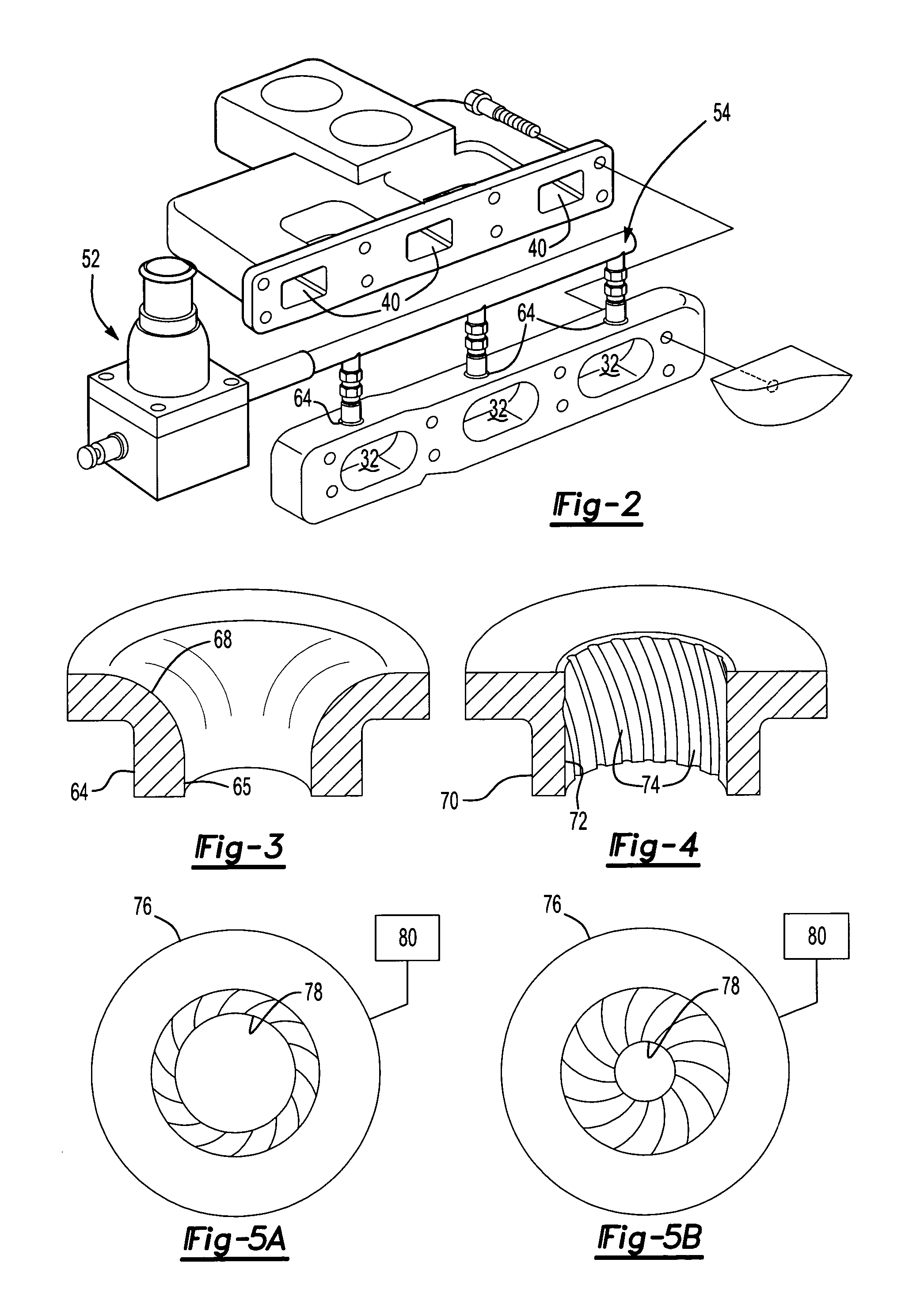
[0030] A primary intake manifold 34 (illustrated only partially) has an interior chamber 36, an inlet end 38 and a plurality of outlet ports 40. The outlet ports 40 are fluidly connected to the engine combustion chamber 32 through intake passageways 41 formed in the engine housing 31 so that each port 40 and each passageway 41 is associated with one or more combustion chambers 32. Thus, during engine cranking, the engine pistons induct air from the inlet 38 of the primary intake manifold 34, through the primary intake manifold interior chamber 36 and the outlet ports 40 and passageways 33 to the combustion chambers 32. A throttle 42 (FIG. 1), illustrated only diagrammatically, is fluidly conne...


PUM


Abstract

A cold start fuel control system is disclosed for use with an internal combustion engine having a plurality of combustion chambers, a source of fuel and an intake manifold having an inlet and an outlet port connected to each combustion chamber. The system includes a cold start fuel injector assembly having an inlet and an outlet to provide a vapor fuel charge during a cold start engine condition. The cold start fuel injector assembly inlet is fluidly connected to the source of fuel. An auxiliary intake manifold has an internal chamber and the cold start fuel injector assembly outlet is fluidly connected to the auxiliary intake manifold chamber. The auxiliary intake manifold chamber is then fluidly connected through a control orifice to each of the combustion chambers at a position downstream from the inlet of the primary intake manifold. A control circuit optionally controls the area of the control orifice to minimize noxious emissions from the engine and a shroud is optionally associated with each control orifice to enhance mixing of the vapor fuel with the inducted airflow to also minimize noxious emissions from the engine.

Description

[0001] This application is a continuation-in-part of U.S. patent application Ser. No. 10 / 094,188 filed Mar. 8, 2002 which is hereby incorporated herein by reference.[0002] I. Field of the Invention[0003] The present invention relates to a cold start fuel control system for an internal combustion engine.[0004] II. Description Of Related Art[0005] Most modern day internal combustion engines of the type used in automotive vehicles include a plurality of internal combustion chambers. A primary intake manifold has one end open to ambient air and its other end open to the combustion chambers through intake ports formed in the engine housing as well as through one or more engine intake valves associated with each combustion chamber.[0006] In order to provide fuel to the engine, a multi-point fuel injector is associated with each of the internal combustion engine chambers. During a warm engine operating condition, the multi-point fuel injectors, under control from the electronic control uni...

Claims


Application Information

Patent Timeline
Patent Type & Authority Applications(United States)
IPC IPC(8): F01N5/02F01P3/20F02M25/07F02M31/08F02M31/093F02M31/10F02M31/135F02M35/10F02M51/02F02M51/08F02M53/02F02M61/18F02M69/00F02M69/32F02N19/04
CPCF02M25/072F02M25/0742F02M31/093F02M31/135Y02T10/126F02M35/10216F02M69/325Y02T10/121Y02T10/146F02M35/10078F02M26/17F02M26/36Y02T10/12
Inventor HUNT, FRANK WARRENMIYAJIMA, AYUMUSAIKALIS, GEORGEBORG, JONATHANOHO, SHIGERU
Owner HITACHI LTD
Why Eureka
Try Eureka