Multi-fluid mixer

A mixer and multi-fluid technology, applied in the direction of machines/engines, engine components, exhaust gas recirculation, etc., can solve the problems of poor mixing effect and low integration, and achieve improved mixing effect, high integration, and high mixing uniformity Effect

Active Publication Date: 2017-09-05
DONGFENG COMML VEHICLE CO LTD
View PDF8 Cites 3 Cited by
  • Summary
  • Abstract
  • Description
  • Claims
  • Application Information

AI Technical Summary

Problems solved by technology

[0006] The purpose of the present invention is to overcome the problems of low integration and poor mixing effect in the prior art, and provide a multi-fluid mixer with high integration and excellent mixing effect

Method used


Image

  • Multi-fluid mixer
  • Multi-fluid mixer
  • Multi-fluid mixer

Examples


Embodiment 1

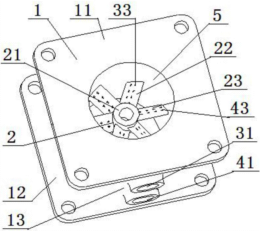
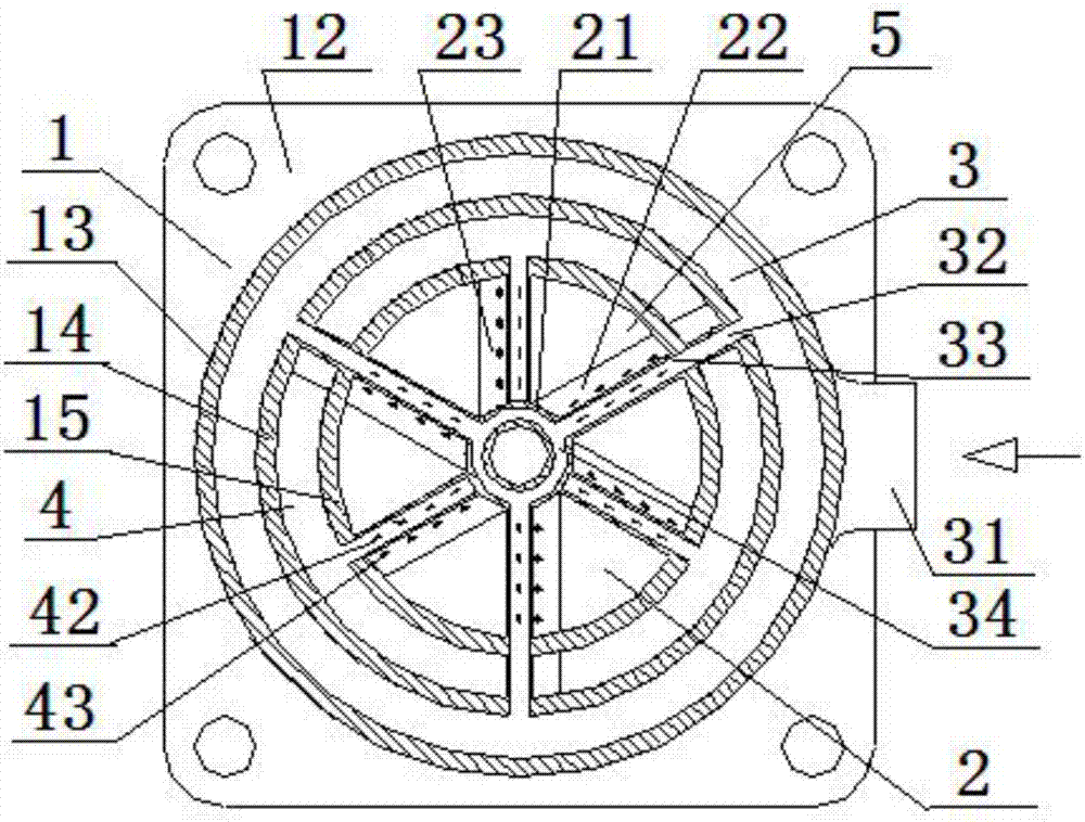
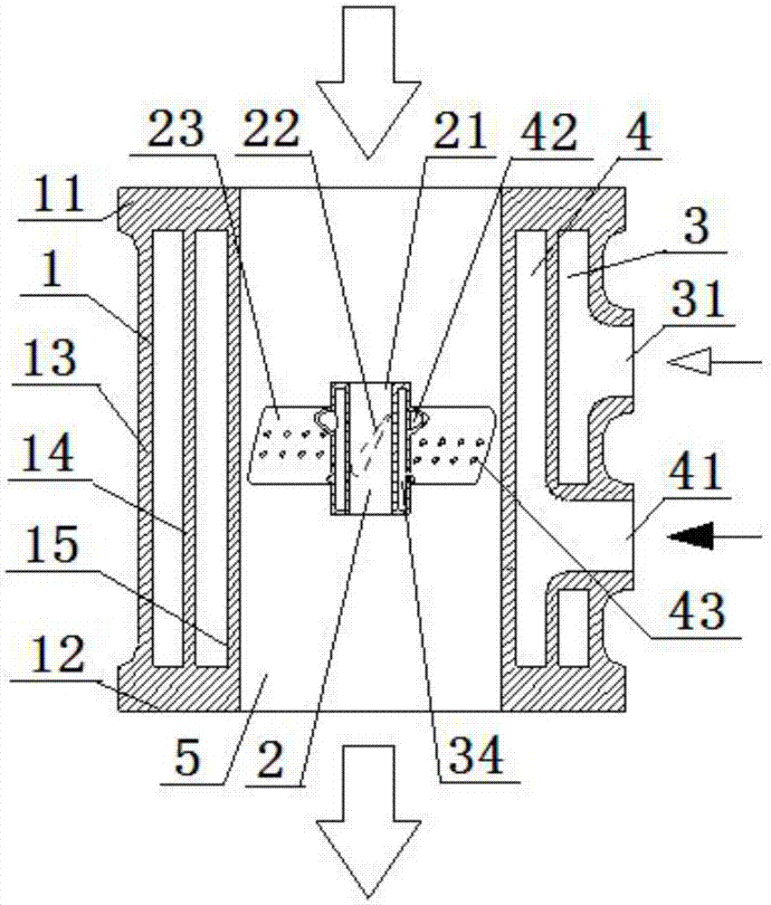
[0058] A multi-fluid mixer, comprising a gas mixing seat 1 and a mixing core 2, the mixing core 2 is arranged inside the gas mixing seat 1, the gas mixing seat 1 includes a top plate 11 and a bottom plate 12, the top plate 11 and the bottom plate 12 An outer cavity wall 13, a middle cavity wall 14, and an inner cavity wall 15 are arranged coaxially therebetween, and a first fluid chamber 3 is formed between the outer cavity wall 13 and the inner cavity wall 14, and the inner cavity wall 14 and the inner cavity A second fluid chamber 4 is formed between the walls 15, the inner chamber wall 15 is a gas mixing chamber 5, and the outer chamber wall 13 is provided with a first fluid inlet 31 and a second fluid inlet 41, The first fluid inlet 31 communicates with the first fluid chamber 3, and the second fluid inlet 41 communicates with the second fluid chamber 4; the mixing core 2 includes a middle support 21, a first fluid mixing vane 22 and the second fluid mixing blade 23, one e...

Embodiment 2

[0060] Embodiment 2 is basically the same as Embodiment 1, and its difference is:

[0061] The middle support 21 is a circular tube structure, and the first fluid mixing vanes 22 and the second fluid mixing vanes 23 are evenly distributed on the outer circumference of the middle support 21; the first fluid mixing vanes 22 and The sum of the number of the second fluid mixing blades 23 is six pieces; the angle between the first fluid mixing blades 22 and the top plate 11 is 60 degrees; the upper and lower sides of the first fluid blade cavity 32 First air mixing holes 33 are opened on the cavity walls, and second air mixing holes 43 are opened on the upper and lower sides of the second fluid vane cavity 42 .

Embodiment 3

[0063] Embodiment 3 is basically the same as Embodiment 2, and its difference is:

[0064] In the pipe wall of the middle support 21, a first fluid mixing cavity 34 is provided, and the first fluid mixing cavity 34 communicates with the first fluid cavity 3 through the first fluid vane cavity 32; the first fluid mixing cavity The cross-sectional shape of the vane 22 is the same as the cross-sectional shape of the second fluid mixing vane 23, and the thickness of the first fluid mixing vane 22 gradually becomes thicker from the side of the top plate 11 to the side of the bottom plate 12, and the main fluid is at the top plate 11. The inflow point, the bottom plate 12 is the outflow point of the main fluid.


PUM


Abstract

The invention relates to a multi-fluid mixer which comprises a gas mixing base and a mixing core. The mixing core is arranged inside the gas mixing base; the gas mixing base comprises a top plate and a bottom plate, an outer cavity wall, a middle cavity wall and an inner cavity wall are coaxially arranged between the top plate and the bottom plate, a first fluid cavity is formed between the outer cavity wall and the middle cavity wall, a second fluid cavity is formed between the middle cavity wall and the inner cavity wall, and a gas mixing cavity is formed inside the inner cavity wall; and the mixing core comprises a middle support, a first fluid gas mixing blade and a second fluid gas mixing blade, one end of the first fluid gas mixing blade is fixedly connected with the outer wall of the middle support, the other end of the first fluid gas mixing blade (22) penetrates the inner cavity wall to be fixedly connected with the middle cavity wall, one end of the second fluid gas mixing blade is fixedly connected with the outer wall of the middle support, and the other end of the second fluid gas mixing blade is fixedly connected with the inner cavity wall. By means of the design, mixing of three kinds of fluid can be achieved, and the uniform mixing integration level is high.

Description

technical field [0001] The invention relates to a fluid mixer, in particular to a multi-fluid mixer, which is particularly suitable for improving mixing efficiency and mixing uniformity. Background technique [0002] At present, in the face of the increasingly severe environmental crisis, the emission regulations of various countries are becoming more and more stringent, and low emission is the main direction of the development of internal combustion engines. EGR as the reduction of internal combustion engine NO x Effective internal purification measures for emissions are also one of the important technologies for gas engines to achieve low emissions. In gas engines, the uniformity of mixing EGR, fuel gas and fresh charge is critical to engine performance. Therefore, a mixer device is usually added to enhance the mixing efficiency of gas, EGR and fresh charge to achieve better mixing uniformity. [0003] The Chinese patent publication number is CN105003361A, and the inven...

Claims


Application Information

Patent Timeline
Patent Type & Authority Applications(China)
IPC IPC(8): F02M26/19
CPCF02M26/19
Inventor 徐敏李卫国陈功军胡前张少华李阳王清明
Owner DONGFENG COMML VEHICLE CO LTD
Why Eureka
Try Eureka