Aseptic beverage bottle filling plant with a clean room arrangement enclosing the aseptic beverage bottle filling plant and a method of operating same, and an aseptic container filling plant with a clean room arrangement enclosing the aseptic container filling plant, and a method of operating same

a technology for aseptic beverage bottles and filling containers, which is applied in the directions of liquid handling, packaging goods, transportation and packaging, etc., can solve the problems of inadequate efficiency of liquid sterilizing media and achieve the effect of significant or somewhat accelerating the method

Inactive Publication Date: 2010-02-25
KHS GMBH
View PDF29 Cites 16 Cited by
  • Summary
  • Abstract
  • Description
  • Claims
  • Application Information

AI Technical Summary

Benefits of technology

[0017]Depending on the machine, it may be necessary or desired to have activation devices immediately or generally downstream of the container sterilization devices, which devices activate the condensation film applied to the inside of the containers by the admissi

Problems solved by technology

Disadvantageous with this type of cleaning is that a plurality of sprayer heads must be arranged in the interior of the machine to enable complete or virtually complete wetting o

Method used


Image

  • Aseptic beverage bottle filling plant with a clean room arrangement enclosing the aseptic beverage bottle filling plant and a method of operating same, and an aseptic container filling plant with a clean room arrangement enclosing the aseptic container filling plant, and a method of operating same
  • Aseptic beverage bottle filling plant with a clean room arrangement enclosing the aseptic beverage bottle filling plant and a method of operating same, and an aseptic container filling plant with a clean room arrangement enclosing the aseptic container filling plant, and a method of operating same
  • Aseptic beverage bottle filling plant with a clean room arrangement enclosing the aseptic beverage bottle filling plant and a method of operating same, and an aseptic container filling plant with a clean room arrangement enclosing the aseptic container filling plant, and a method of operating same

Examples


Embodiment Construction

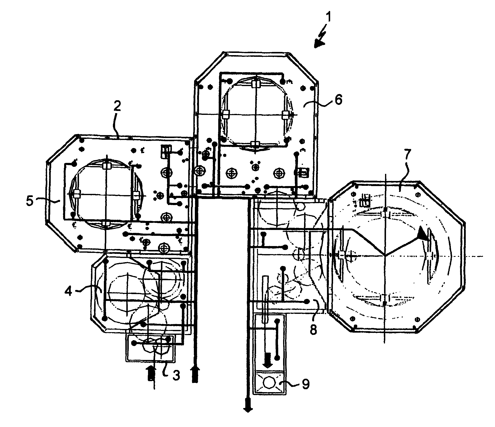
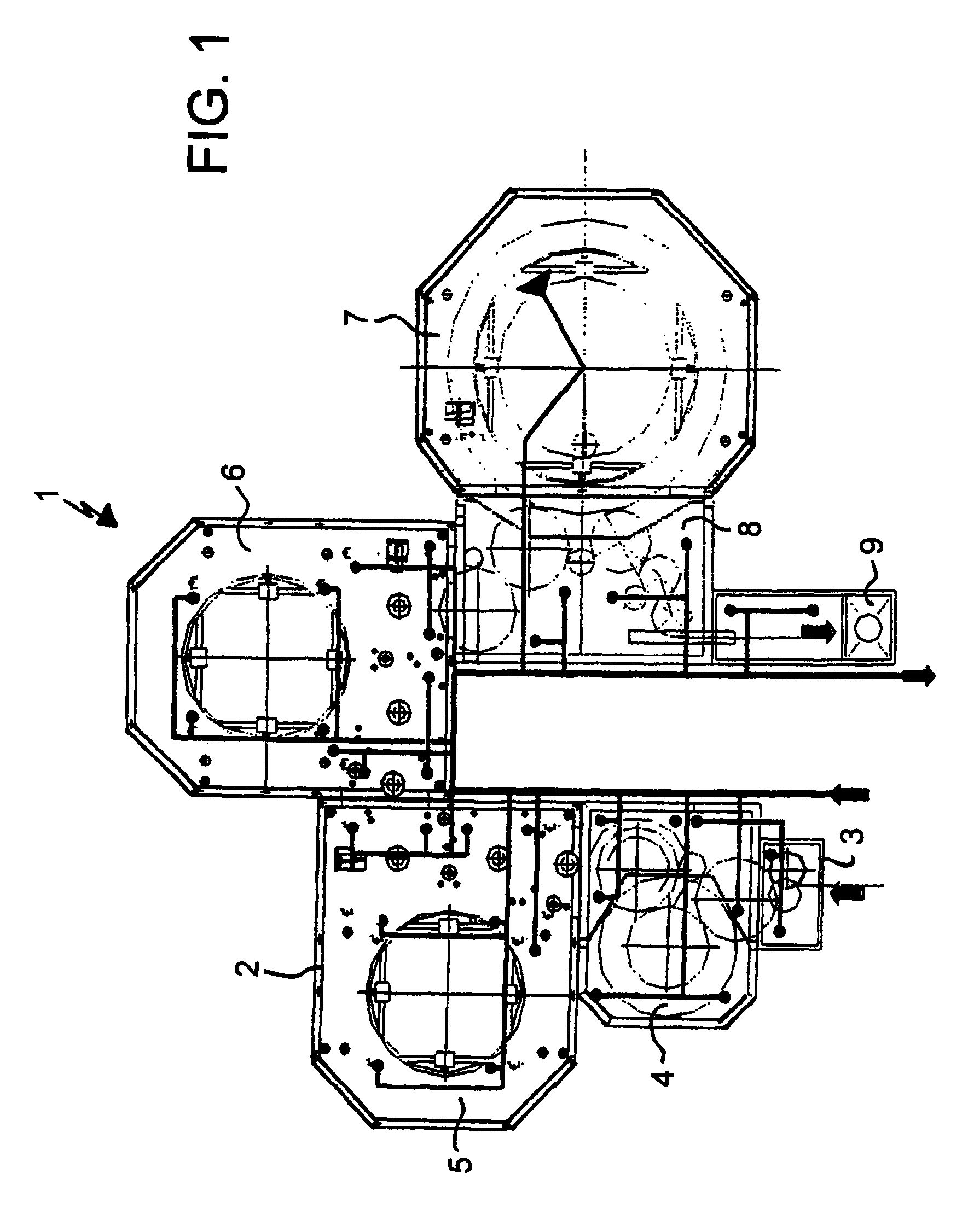
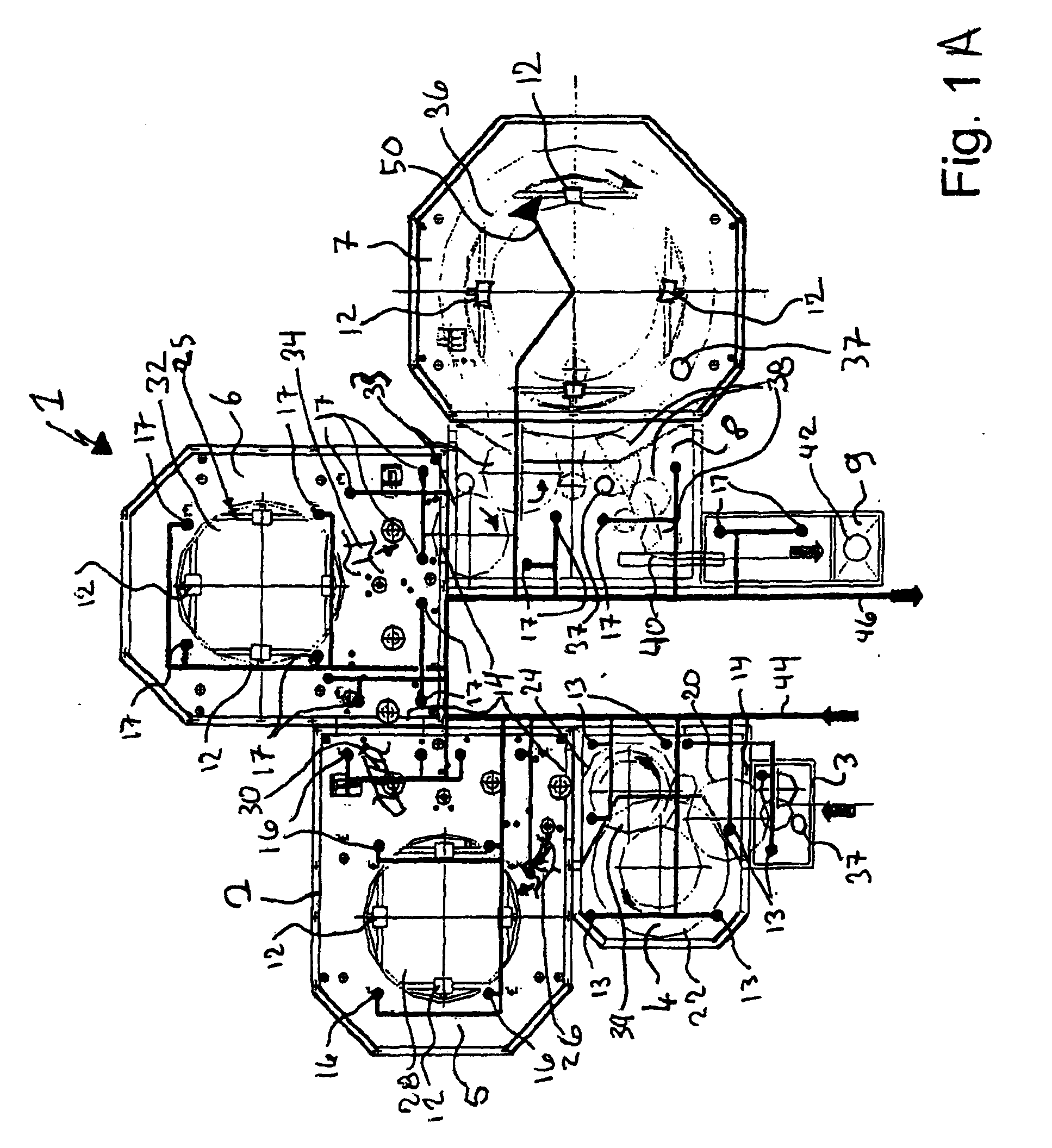
[0032]A machine designated in its entirety as 1 for the filling of containers, for example for bottles or cans with beverages, etc., is shown in greater detail in FIGS. 1 and 1A. The complete machine is enclosed in a housing 2, which protects the entire interior from contaminants from the outside so that clean room conditions prevail in the interior.

[0033]The machine 1 has a container opening 3, through which the bottles to be filled can gain admission to the interior of the machine. The containers are then sterilized in a sterilization device 4. They move around a circular track together with a plurality of vaporization heads that direct vaporous H2O2 into the interior and the upper outer region of the container. Due to the temperature differences between the vaporized H2O2 and the wall of the container, the sterilizing agent precipitates and forms a condensation film. The containers are then conveyed into a first activation device 5, in which hot air or hot steam is directed again...


PUM

PropertyMeasurementUnit
Flow rateaaaaaaaaaa
Distanceaaaaaaaaaa

Abstract

An aseptic beverage bottle filling plant with a clean room arrangement enclosing the aseptic beverage bottle filling plant and a method of operating same, and an aseptic container filling plant with a clean room arrangement enclosing the aseptic container filling plant, and a method of operating same. The abstract of the disclosure is submitted herewith as required by 37 C.F.R. §1.72(b). As stated in 37 C.F.R. §1.72(b): A brief abstract of the technical disclosure in the specification must commence on a separate sheet, preferably following the claims, under the heading “Abstract of the Disclosure.” The purpose of the abstract is to enable the Patent and Trademark Office and the public generally to determine quickly from a cursory inspection the nature and gist of the technical disclosure. The abstract shall not be used for interpreting the scope of the claims. Therefore, any statements made relating to the abstract are not intended to limit the claims in any manner and should not be interpreted as limiting the claims in any manner.

Description

CONTINUING APPLICATION DATA[0001]This application is a Continuation-In-Part application of International Patent Application No. PCT / EP2007 / 006805, filed on Aug. 1, 2007, which claims priority from Federal Republic of Germany Patent Application No. 10 2006 036 475.9, filed on Aug. 4, 2006. International Patent Application No. PCT / EP2007 / 006805 was pending as of the filing date of this application. The United States was an elected state in International Patent Application No. PCT / EP2007 / 006805.BACKGROUND[0002]1. Technical Field[0003]The present application relates to an aseptic beverage bottle filling plant with a clean room arrangement enclosing the aseptic beverage bottle filling plant and a method of operating same, and an aseptic container filling plant with a clean room arrangement enclosing the aseptic container filling plant, and a method of operating same.[0004]2. Background Information[0005]Background information is for informational purposes only and does not necessarily adm...

Claims


Application Information

Patent Timeline
IPC IPC(8): B65B1/04B08B9/00
CPCA61L2/208A61L2/22A61L2202/17B67C2003/228B65B55/027B65B55/10B67C3/22A61L2202/23B67C3/005
Inventor SANGI, DARYOUSHHEROLD, THOMAS
Owner KHS GMBH
Why Eureka
Try Eureka