Soft magnetic material, dust core, method for manufacturing soft magnetic material, and method for manufacturing dust core

a technology of soft magnetic material and dust core, which is applied in the direction of magnetic bodies, natural mineral layered products, synthetic resin layered products, etc., can solve the problems of power conversion efficiency drop, output decrease, and impedance drop, and achieve the effect of improving dc bias characteristics

Active Publication Date: 2010-02-25
SUMITOMO ELECTRIC IND LTD
View PDF5 Cites 31 Cited by
  • Summary
  • Abstract
  • Description
  • Claims
  • Application Information

AI Technical Summary

Benefits of technology

[0112]The soft magnetic material, the dust core, the method for manufacturing the soft magnetic material, and the method for manufacturing the dust core according to the present invention can be applied to, for example, an iron core of a static apparatus such as a transformer, a choke coil, or an inverter.

Problems solved by technology

As a result, the impedance decreases, thereby causing a problem in that, for example, an output decreases or a power conversion efficiency drops.
However, dust cores are inferior to magnetic steel sheets in terms of DC bias characteristics.

Method used


Image

  • Soft magnetic material, dust core, method for manufacturing soft magnetic material, and method for manufacturing dust core
  • Soft magnetic material, dust core, method for manufacturing soft magnetic material, and method for manufacturing dust core
  • Soft magnetic material, dust core, method for manufacturing soft magnetic material, and method for manufacturing dust core

Examples


examples

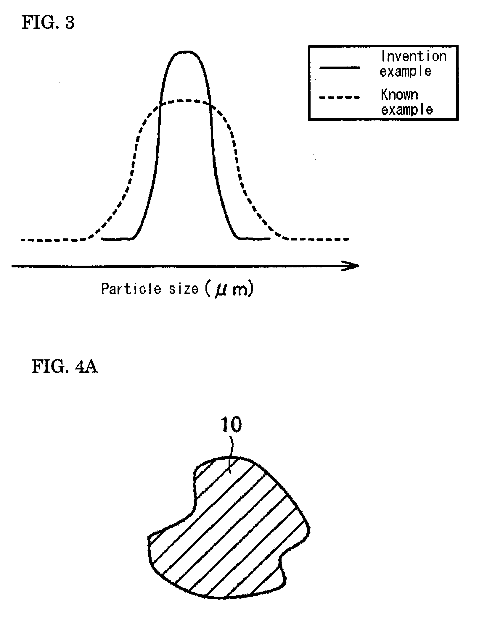
[0098]In these Examples, an effect provided by including metal magnetic particles whose coefficient of variation Cv (σ / μ) is 0.40 or less and circularity Sf is 0.80 or more was examined.

examples 1 to 4

[0099]In Example 1, the soft magnetic material manufactured by the method described in the embodiment above was used. Specifically, in the preparation step (S11), a metal magnetic particle containing 99.6% by weight or more of iron and the balance that is composed of incidental impurities such as 0.3% by weight or less of 0 and 0.1% by weight or less of C, N, P, Mn, or the like was prepared by water-atomizing an iron powder. The average particle sizes of the metal magnetic particles in Examples 1 to 4 were selected as described in Table. The coefficient of variation Cv and the circularity Sf of the metal magnetic particles in Examples 1 to 4 were as described in Table. The coefficient of variation Cv of the metal magnetic particles was calculated by measuring the particle size distribution of the targeted soft magnetic material (a plurality of metal magnetic particles) using a laser diffraction / scattering particle size distribution analysis method. The circularity Sf was statistical...


PUM

PropertyMeasurementUnit
particle sizeaaaaaaaaaa

Abstract

A soft magnetic material, a dust core, a method for manufacturing the soft magnetic material, and a method for manufacturing the dust core that can improve DC bias characteristics are provided.A soft magnetic material includes a plurality of metal magnetic particles 10 whose coefficient of variation Cv (σ / μ), which is a ratio of a standard deviation (σ) of a particle size of the metal magnetic particles 10 to an average particle size (μ) thereof, is 0.40 or less and whose circularity Sf is 0.80 or more and 1 or less. The metal magnetic particles 10 preferably have an average particle size of 1 μm or more and 70 μm or less. The soft magnetic material preferably further includes an insulating coated film that surrounds a surface of each of the metal magnetic particles 10.

Description

TECHNICAL FIELD[0001]The present invention relates to a soft magnetic material, a dust core, a method for manufacturing the soft magnetic material, and a method for manufacturing the dust core. For example, the present invention relates to a soft magnetic material that does not easily cause magnetic saturation and provides excellent direct current (DC) bias characteristics when used for a magnetic core of an inverter or the like, a dust core, a method for manufacturing the soft magnetic material, and a method for manufacturing the dust core.BACKGROUND ART[0002]A magnetic steel sheet has been used as a soft magnetic material utilized for an iron core of a static apparatus such as a transformer, a choke coil, and an inverter. However, a dust core is investigated as an alternative material of the magnetic steel sheet.[0003]In general, the waveform of a current applied to a coil of a static apparatus includes a direct-current component together with an alternating-current component. Whe...

Claims


Application Information

Patent Timeline
Patent Type & Authority Applications(United States)
IPC IPC(8): H01F1/04B32B5/16B05D7/00B22F1/00B22F1/02B05D5/00B22F1/052B22F1/102B22F1/105
CPCB22F1/0014Y10T428/2982B22F1/007B22F2999/00C22C38/00C22C2202/02H01F1/24H01F1/26H01F1/33H01F3/02H01F41/0246B22F1/0062B22F3/10B22F2201/02B22F1/052B22F1/102B22F1/105
Inventor ISHIMINE, TOMOYUKISAKAMOTO, TOSHIHIROMAEDA, TORUIGARASHI, NAOTO
Owner SUMITOMO ELECTRIC IND LTD
Why Eureka
Try Eureka