[0081] The intermediate layer may contain additives) for imparting various functions so long as it remains substantially transparent. The
transmittance at 550 nm of the intermediate layer is preferably 70% or more, still preferably 80% or more. For example, it may contain a
dielectric such as
barium titanate particles, an
electrically conductive material such as
tin oxide,
indium oxide,
tin oxide-
indium or
metal particles, a dye, a fluorescent dye or a fluorescent
pigment. Moreover, it may contain light-emitting particles to such an extent that the
advantage of the invention is not damaged thereby (i.e. in an amount attaining not more than 30% of the brightness of the total electroluminescent phosphor).
[0082] The intermediate layer may be made of an
inorganic compound such as SiO2, another
metal oxide or a
metal nitride. To form the intermediate layer with the use of an
inorganic compound, it is possible to employ the
sputtering method, the CVD method, etc. In the case of forming the intermediate layer with the use of an
inorganic compound, the thickness is preferably more than 10 nm but not more than 1 μm, still preferably more than 10 nm but not more than 200 nm. It is also favorable that the intermediate layer is composed of an inorganic compound layer and an
organic polymer compound layer.
[0083] It is preferable that the EL device of the invention has at least one intermediate layer containing an
organic polymer compound and having a thickness of 0.5 μm or more but not more than 10 μm. It is preferable that the
organic polymer compound is one selected from among polyesters, polycarbonates, polyamdies, polyether sulfones, fluorinated rubbers, polyacrylates, polymethacrylates, polyacrylic amides, polymethacrylic amides,
silicone resins, cyanoethylpullulan, cyanoethyl
polyvinyl alcohol, cyanoethylsaccharose, UV-curable resins obtained from polyfunctional
acrylate compounds and heat-curable resins obtained from
epoxy compounds or
cyanate compounds and so on. Among these compounds, one having a
softening point of 70° C. or above (still preferably 100° C. or above) is preferred. It is also preferable to use a combination of two or more
polymer compounds selected from those cited above.
[0084] In the case where the organic
polymer compound employed in the intermediate layer has a high
softening point (for example, 200° C. or above), it is also preferred to use another intermediate layer containing an organic
polymer compound having a lower
softening point so as to improve the adhesiveness to the transparent
electrode layer of the phosphor particle-containing layer.
[0085] To achieve
white light emission, a
red light-emitting material is employed together with bluish
green light-emitting
zinc sulfide particles in the electroluminescent device of the invention. The
red light-emitting material may be dispersed in the phosphor particle layer. Alternatively, it may be dispersed in the
dielectric layer. It may be provided either between the phosphor particle layer and the transparent
electrode or in the opposite side to the phosphor particle layer concerning the transparent
electrode.
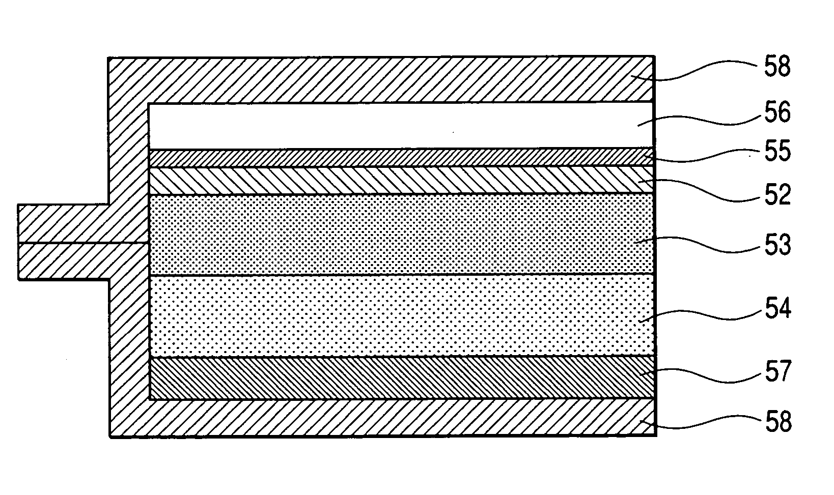
[0086] In the electroluminescent device of the invention, the
light emission wavelength in emitting
white light is preferably 600 nm or more but not more than 650 nm. To obtain
red light wavelength falling within this range, the red light-emitting material may be contained in the phosphor particle layer, or provided between the phosphor particle layer and the transparent electrode or in the opposite side to the phosphor particle layer concerning the transparent electrode. It is most preferable that the red light-emitting material is contained in the
dielectric layer. Although it is preferable that the whole
dielectric layer in the electroluminescent device of the invention serves a
dielectric layer containing the red light-emitting material, it is more preferable that the dielectric layer in the device is divided in two or more
layers and a part thereof serves as a layer containing the red light-emitting material. It is preferable that the layer containing the red light-emitting material is provided between the dielectric layer and the phosphor particle layer. It is also preferred that the layer containing the red light-emitting material is sandwiched between dielectric
layers free from the red light-emitting material. In the case where the layer containing the red light-emitting material is located between the dielectric layer free from the red light-emitting material and the phosphor particle layer, the thickness of the layer the red light-emitting material is preferably 1 μm or more but not more than 20 μm, still preferably 3 μm or more but not more than 17 μm. The concentration of the red light-emitting material in the dielectric layer containing the red light-emitting material is preferably 1% by weight or more but not more than 20% by weight, still preferably 3% by weight or more but not more than 15% by weight, based on the dielectric particles. In the case where the layer containing the red light-emitting material is sandwiched between dielectric layers free from the red light-emitting material, the thickness of the layer containing that the layer containing the red light-emitting material is preferably 1 μm or more but not more than 20 μm, still preferably 3 μm or more but not more than 10 μm. The concentration of the red light-emitting material in the dielectric layer containing the red light-emitting material is preferably 1% by weight or more but not more than 30% by weight, still preferably 3% by weight or more but not more than 20% by weight, based on the dielectric particles. In the case where the layer containing the red light-emitting material is sandwiched between dielectric layers free from the red light-emitting material, it is also preferable that the layer containing the red light-emitting material is free from dielectric particles but composed exclusively of a highly dielectric binder and the red light-emitting material.

