Image pickup apparatus, display and image processing apparatus

a technology of image processing and image pickup, which is applied in the field of image pickup apparatus, display and image processing apparatus, can solve the problems of difficulty in changing the number of unit images corresponding to the number of microlenses

Inactive Publication Date: 2010-02-25
SONY CORP
View PDF5 Cites 28 Cited by
  • Summary
  • Abstract
  • Description
  • Claims
  • Application Information

AI Technical Summary

Benefits of technology

[0008]It is desirable to provide an image pickup apparatus, a display and an image processing apparatus which are capable of changing the number of unit images each formed for each microlens in image pickup data obtained so as to include information on the traveling direction of a light ray.

Problems solved by technology

In the case where a resizing process is performed on image pickup data obtained by the above-described technique, it is difficult to change the number of unit images corresponding to the number of microlenses.

Method used


Image

  • Image pickup apparatus, display and image processing apparatus
  • Image pickup apparatus, display and image processing apparatus
  • Image pickup apparatus, display and image processing apparatus

Examples


modification 1

[0061]FIGS. 8A and 8B are schematic views for describing another resizing operation in the resizing section 144 of the above-described image processing section 14. FIG. 9 is a schematic view of image data D5 obtained by performing, in the rearranging section 145, a rearranging process on image data D4 obtained by the resizing process in FIGS. 8A and 8B.

[0062]In this modification, as illustrated in FIG. 8A, the resizing section 144 performs a resizing process in which the resolution (6×6) of each of the parallax images D11 to D19 is increased (hereinafter referred to as an image upsizing process). The image upsizing process is achieved, for example, by performing various pixel interpolation processing such as bicubic interpolation processing. Thereby, as illustrated in FIG. 8B, parallax images D41 to D49 with an increased resolution of, for example, 9×9 are produced. The produced parallax images D41 to D49 are inputted into the rearranging section 145 as image data D4.

[0063]In the re...

modification 2

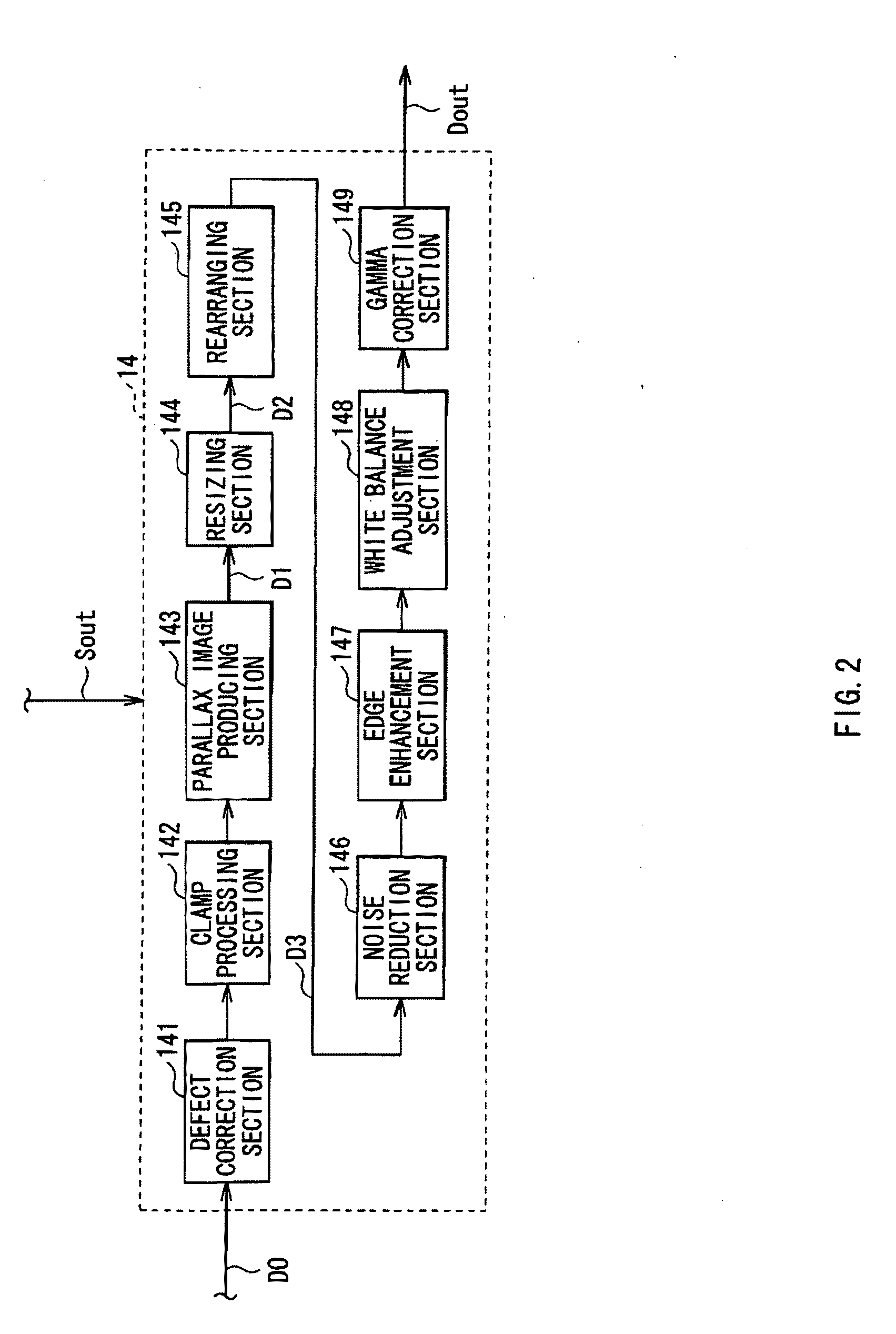
[0064]FIG. 10 is a functional block diagram of the whole configuration of an image processing section 24 according to Modification 2. In the modification, the rearranging section 145 in the image processing section 14 according to the embodiment is not included. More specifically, the parallax image producing section 143 produces parallax images on the basis of the image pickup data D0, and then the resizing section 144 performs a resizing process on the basis of the parallax images. Then, the image data D2 obtained by the resizing process is not supplied to the rearranging section 145, and the noise reduction section 146, the edge enhancement section 147, the white balance adjustment section 148 and the gamma correction section 149 each perform predetermined processing on the image data D2, and the processed image data D2 is outputted as image data Dout2.

[0065]Thus, in the image processing section 24, the rearranging section 145 may not be included. In other words, a plurality of p...

modification 3

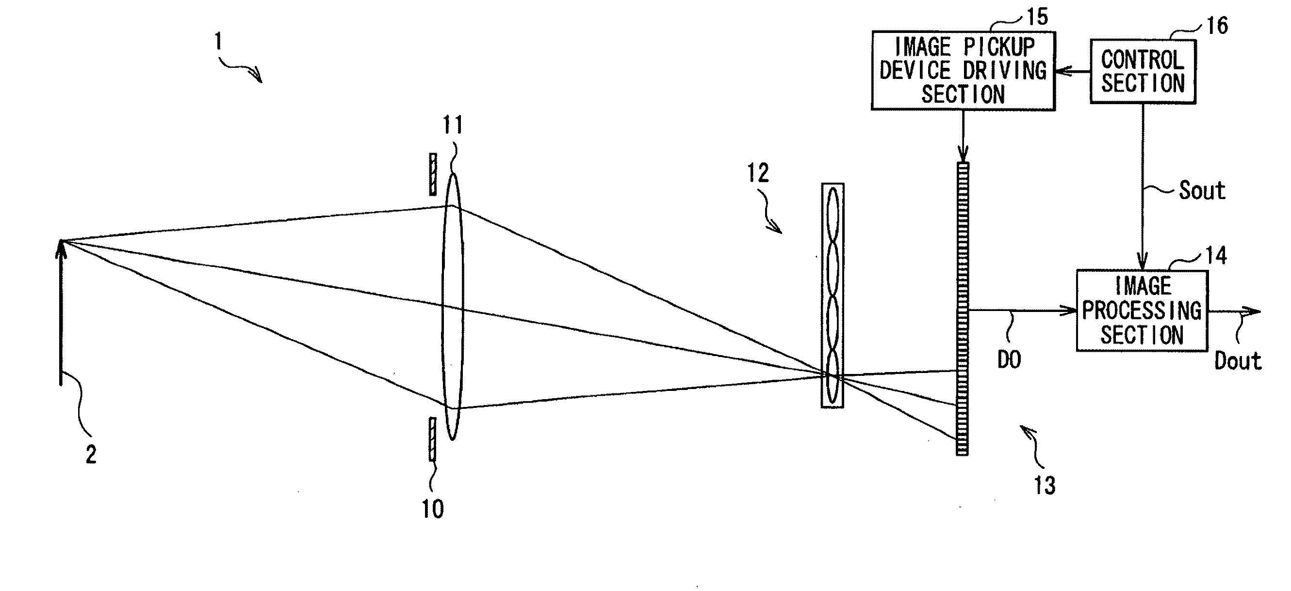
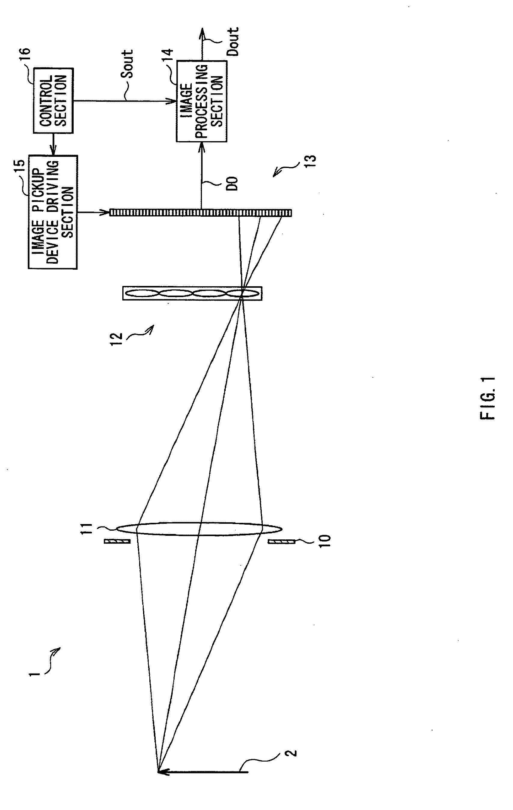
[0079]FIG. 13 is a functional block diagram of the whole configuration of an image processing section 25 according to Modification 3 of the embodiment. The image processing section 25 performs predetermined image processing on the basis of the image pickup data D0 obtained by the image pickup optical system of the image pickup apparatus 1 according to the embodiment. The image processing section 25 has the same configuration as that of the image processing section 23, except that the flipping process by the flipping section 150 is performed between the parallax image producing process by the parallax image producing section 143 and the resizing process by the resizing section 144. In other words, when the image data D1 as a plurality of parallax images is inputted into the flipping section 150, the flipping process is performed on each of the plurality of parallax images to obtain image data D4. The resizing process by the resizing section 144 and the rearranging process by the rear...


PUM


Abstract

An image pickup apparatus includes: an image pickup lens; an image pickup device to obtain image pickup data; a microlens array on an image forming plane of the image pickup lens; and an image processing section producing an image based on the image pickup data. The microlens array includes microlenses each provided corresponding to pixels of the image pickup device. The image processing section includes a parallax image producing section and a resizing section. The parallax image producing section extracts pixel data from the image pickup data and synthesizes the pixel data to produce a plurality of parallax images. Each of the extracted pixel data corresponds to each of pixels located at the same position in image pickup regions of the image pickup device, each region corresponding to each microlens. The resizing section resizes each parallax image to change the resolutions thereof.

Description

BACKGROUND OF THE INVENTION[0001]1. Field of the Invention[0002]The present invention relates to an image pickup apparatus, a display and an image processing apparatus which each include a microlens array.[0003]2. Description of the Related Art[0004]Various image pickup apparatuses have been proposed and developed. An image pickup apparatus performing predetermined image processing on image pickup data obtained by picking up an image to output the processed image pickup data has been also proposed.[0005]For example, International Patent Publication No. 06 / 039486 and Ren. Ng, et al. “Light Field Photography with a Hand-Held Plenoptic Camera”, Stanford Tech Report CTSR 2005-02 propose image pickup apparatuses using a technique called “Light Field Photography”. The image pickup apparatus includes an image pickup lens, a microlens array, an image pickup device and an image processing section, and image pickup data obtained from the image pickup device includes the intensity distribution...

Claims


Application Information

Patent Timeline
Patent Type & Authority Applications(United States)
IPC IPC(8): H04N5/225
CPCH04N5/2254H04N5/2628H04N5/228G02B27/0075H04N23/40H04N23/60
Inventor YAMAMOTO, KENJIHAYASAKA, KENGO
Owner SONY CORP
Why Eureka
Try Eureka