Optical distance measuring sensor and electronic device

a technology of optical distance measurement and electronic device, which is applied in the direction of distance measurement, height/levelling measurement, instruments, etc., can solve the problems of increasing the size of optical distance measurement sensor, complicated operation in various steps, and low accuracy of distance measurement, so as to reduce the size and high the effect of measurement accuracy

Active Publication Date: 2010-02-25
SHARP KK
View PDF6 Cites 40 Cited by
  • Summary
  • Abstract
  • Description
  • Claims
  • Application Information

AI Technical Summary

Benefits of technology

[0015]An object of the invention is to provide inexpensively an optical distance measuring sensor having reduced sizes and a high accuracy of measurement as well as an electronic device including the sensor.
[0017]According to the above structure, since the light receiving unit that collects the light reflected by the target object has the plurality of cells, the accurate measurement can be performed without excessively increasing the distance (A) between the lenses as well as the focal distance (f) between the light receiving unit and the lens on the light receiving side. Therefore, the optical distance measuring sensor having reduced sizes and a high measurement accuracy can be obtained inexpensively.
[0035]As described above, the invention can inexpensively provide the optical distance measuring sensor having the reduced sizes and the high accuracy of measurement as well as the electronic device including the sensor.

Problems solved by technology

Therefore, an accuracy of distance measurement is high when a distance to the object is short, but the accuracy of distance measurement is low when the distance to the object is long.
However, the increase in such distances (A) and (f) results in increase in size of the optical distance measuring sensor.
Consequently, the structure in Japanese Patent Laying-Open No. 2002-195807 suffers from a problem that the distance measuring sensor has large sizes as well as problems that production steps are large in number, operations in various steps are complicated when high accuracies are required, and a production cost is high.

Method used


Image

  • Optical distance measuring sensor and electronic device
  • Optical distance measuring sensor and electronic device
  • Optical distance measuring sensor and electronic device

Examples


Embodiment Construction

[0049]Embodiments of the invention will now be described with reference to the drawings. In the following description, the same or corresponding portions bear the same reference numbers, and description thereof is not repeated.

[0050]When the following description of the embodiment(s) refers to numbers of parts, quantities and / or the like, the scope of the invention is not necessarily restricted to such numbers, quantities and / or the like unless otherwise specified. Each of components of the following embodiment(s) is not essential in the invention unless otherwise specified. When a plurality of embodiments are described below, an appropriate combination of the structures of such embodiments can be originally envisaged unless otherwise specified.

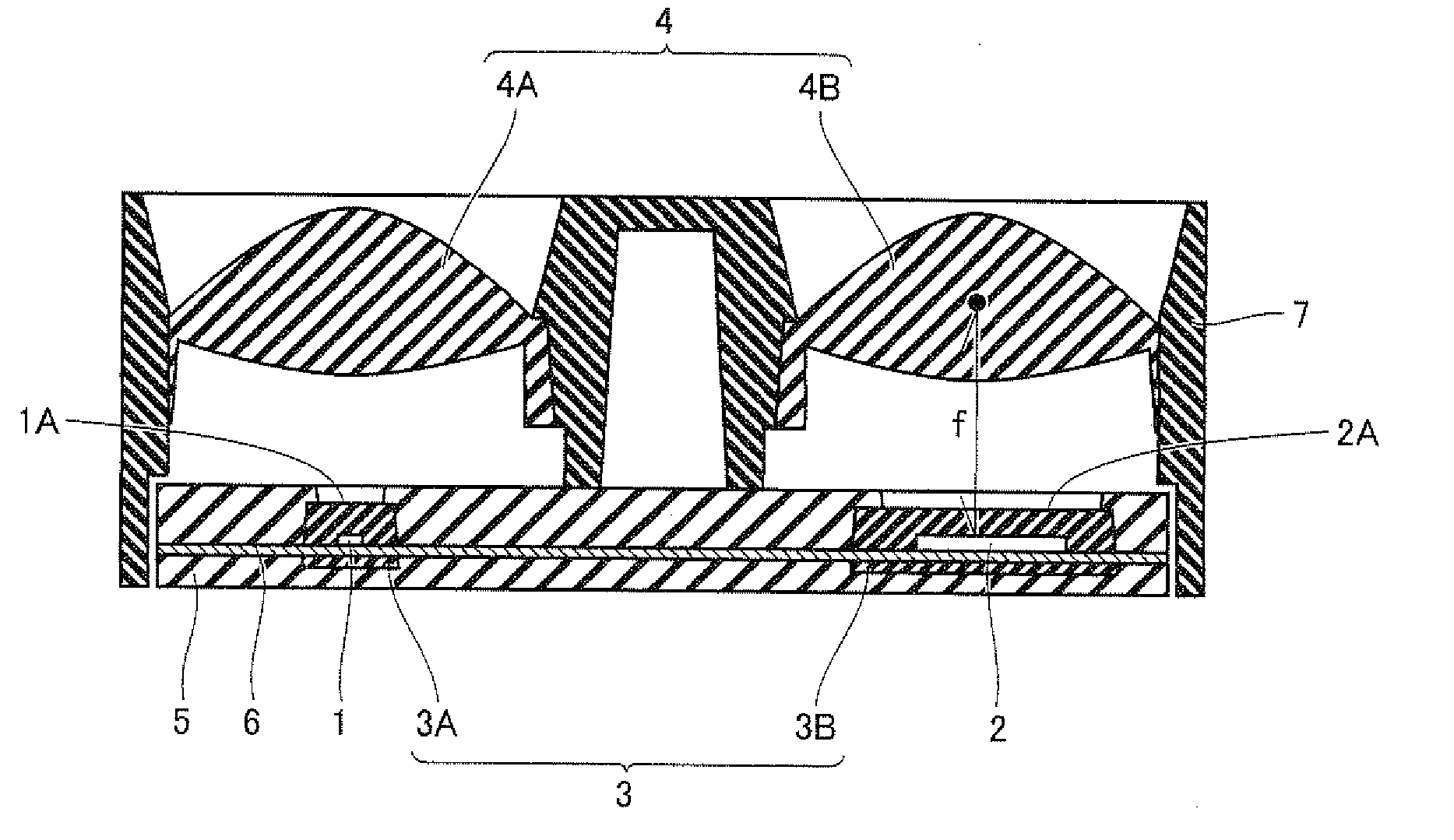
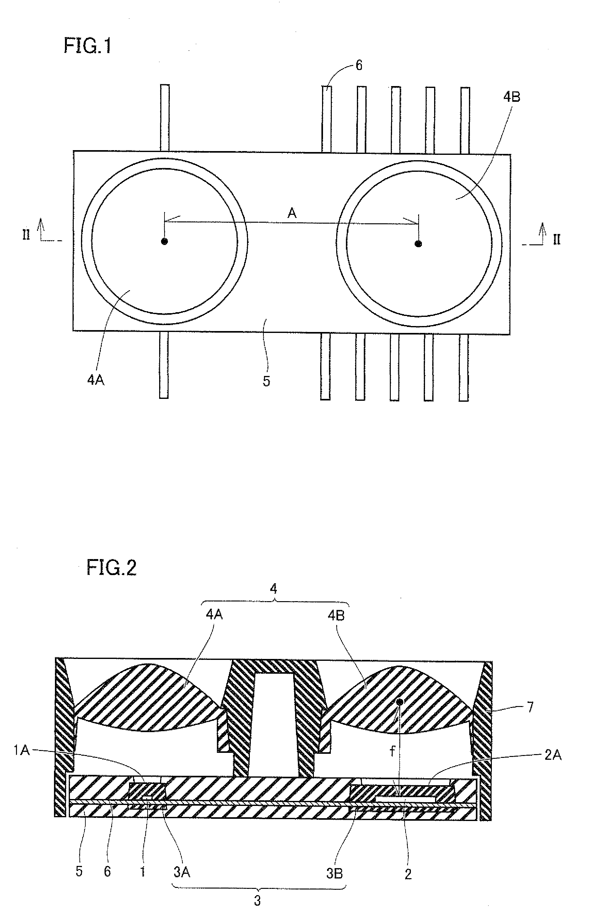
[0051]FIG. 1 is a top view of an optical distance measuring sensor according to an embodiment of the invention. FIG. 2 is a cross section taken along line II-II in FIG. 1.

[0052]Referring to FIGS. 1 and 2, the optical distance measuring sensor...


PUM


Abstract

An optical distance measuring sensor includes a light receiving element arranged on the same plane as a light emitting element. The light receiving element includes a light receiving unit having a plurality of cells and collecting the light emitted from the light emitting element and reflected by a target object, a flash memory unit storing a predetermined position on the light receiving unit, and a signal processing circuit unit sensing the collection position of the light on the light receiving unit, and measuring the distance to the target object based on a relative positional relationship between the predetermined position stored in the flash memory unit and the collection position of the light on light receiving unit.

Description

[0001]This nonprovisional application is based on Japanese Patent Application No. 2008-211796 filed on Aug. 20, 2008 with the Japan Patent Office, the entire contents of which are hereby incorporated by reference.BACKGROUND OF THE INVENTION[0002]1. Field of the Invention[0003]The present invention relates to an optical distance measuring sensor and an electronic device, and particularly to an optical distance measuring sensor for measuring a distance to a target object located within a predetermined range as well as an electronic device including the sensor.[0004]2. Description of the Background Art[0005]There have been known optical distance measuring sensors for measuring a distance to a target object located within in a predetermined range by a triangulation method. FIG. 13 is a cross section showing a conventional optical distance measuring sensor.[0006]Referring to FIG. 13, the conventional optical distance measuring sensor includes a light emitting element 100, a light receivi...

Claims


Application Information

Patent Timeline
Patent Type & Authority Applications(United States)
IPC IPC(8): G01C3/08
CPCG01B11/026G01S17/48G01S7/481G01C3/08
Inventor YAMAGUCHI, AKIFUMIKUBO, MASARUFUKUSHIMA, TOSHIHIKO
Owner SHARP KK
Why Eureka
Try Eureka