Channel arrangement method and radio communication base station device

Active Publication Date: 2010-02-25
PANASONIC HLDG CORP
View PDF10 Cites 23 Cited by
  • Summary
  • Abstract
  • Description
  • Claims
  • Application Information

AI Technical Summary

Benefits of technology

[0015]According to the present invention, a fall in utilization efficiency of a channel communication resource for performing frequency diversity transmis

Problems solved by technology

On the other hand, frequency scheduling transmission requires feedback of received quality information from each mobile station, and is therefore not suitable for data communication when a mobile station is moving at high speed.
On th

Method used


Image

  • Channel arrangement method and radio communication base station device
  • Channel arrangement method and radio communication base station device
  • Channel arrangement method and radio communication base station device

Examples


embodiment 1

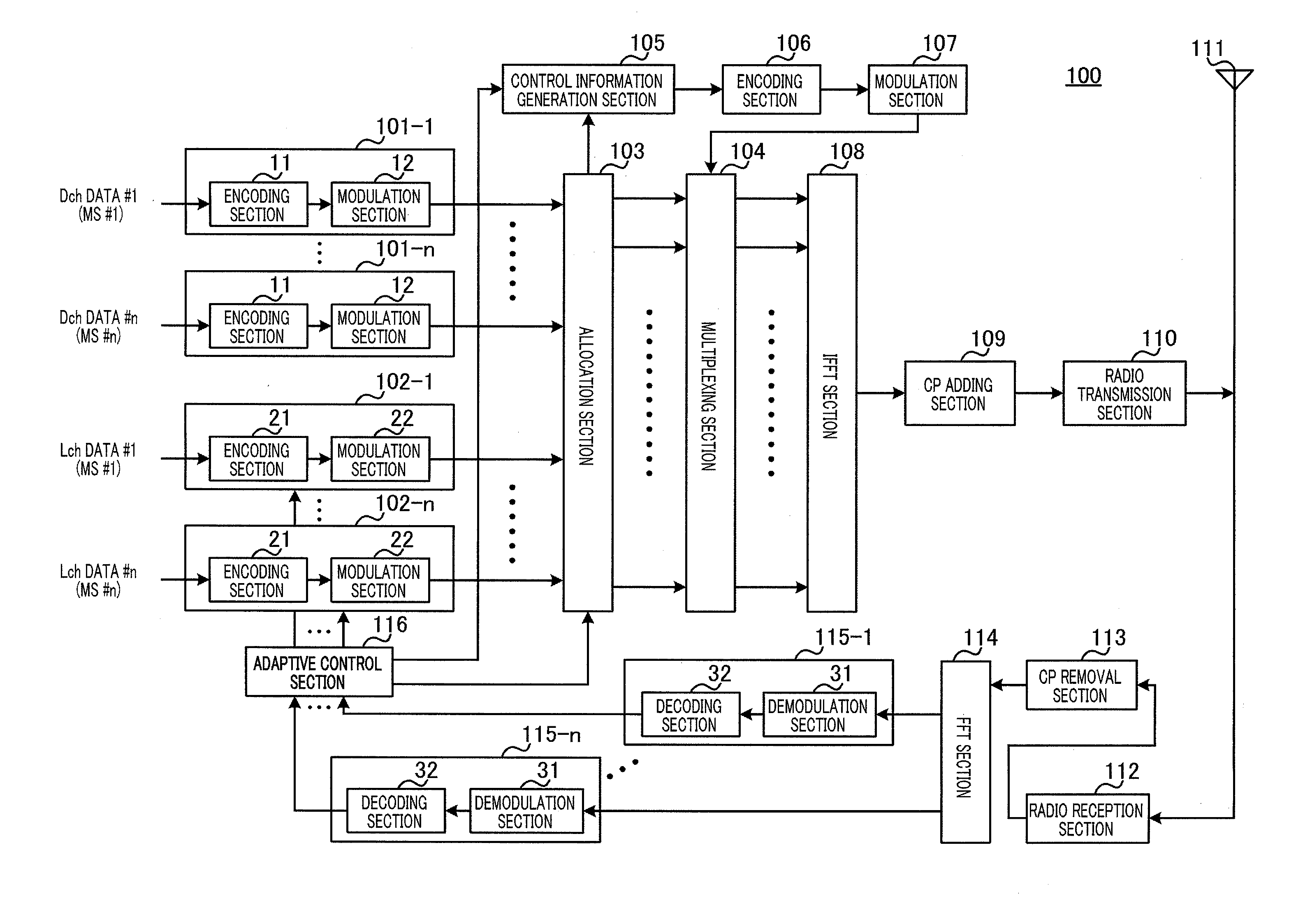
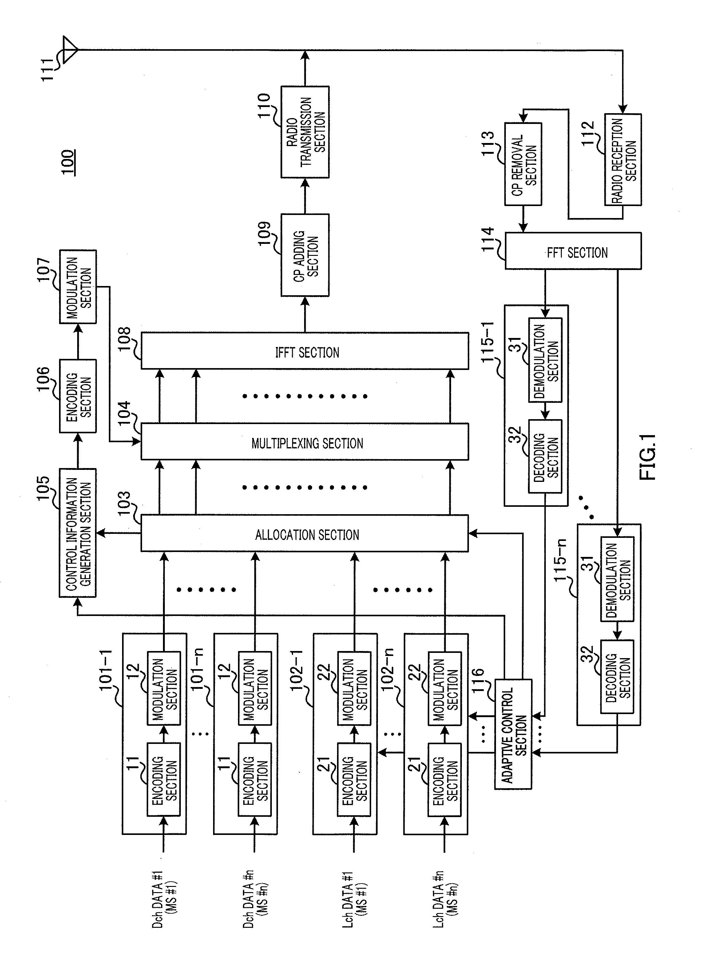
[0044]The configuration of base station 100 according to this embodiment is shown in FIG. 1. Base station 100 divides a plurality of subcarriers comprised of an OFDM symbol that is a multicarrier signal into a plurality of RBs, and uses a Dch and Lch on an RB-by-RB basis in that plurality of RBs. Also, either a Dch or an Lch is allocated to one mobile station in the same subframe.

[0045]Base station 100 is equipped with n encoding and modulation sections 101-1 through 101-n each comprising encoding section 11 and modulation section 12 for Dch data, n encoding and modulation sections 102-1 through 102-n each comprising encoding section 21 and modulation section 22 for Lch data, and n demodulation and decoding sections 115-1 through 115-n each comprising demodulation section 31 and decoding section 32, where n is a number of mobile stations (MSs) with which base station 100 can communicate.

[0046]In encoding and modulation sections 101-1 through 101-n, encoding section 11 performs turbo...

embodiment 2

[0143]In this embodiment a case will be described in which switching between use of Arrangement Method 1 and Arrangement Method 2 of Embodiment 1 is performed according to the communication environment.

[0144]As described above, Arrangement Method 1 enables more RBs consecutive in the frequency domain that can be used for Lch's to be secured than Arrangement Method 2, while Arrangement Method 2 has a greater frequency diversity effect than Arrangement Method 1.

[0145]Specifically, when four consecutive Dch's, Dch #1 through #4, are used for a Dch data symbol of one mobile station, with Arrangement Method 1 (FIG. 5) four RBs consecutive in the frequency domain, RB #3 through #6 and RB #9 through #12, can be used for an Lch, while a Dch data symbol is allocated to two RBs consecutive in the frequency domain, RB #1, #2 and RB #7, #8. On the other hand, with Arrangement Method 2 (FIG. 9) only two RBs consecutive in the frequency domain, RB #2, #3, RB #5, #6, RB #8, #9, and RB #11, #12, ca...

embodiment 3

[0181]In this embodiment a case will be described in which only one Dch is arranged in one RB (the number of subblock divisions per RB is one).

[0182]First, a relational expression for a Dch channel number and the RB number of an RB in which that Dch is arranged will be shown.

[0183]RB number j of an RB in which a Dch with channel number k is arranged is given by Equation (3) below.

[3]

j=q(k)  (Equation 3)

[0184]where k=1, 2, . . . , Nrb, and q(k) is given by an M-row×(Nrb / M)-column block interleaver where M is an arbitrary positive integer.

[0185]If it is assumed here that Nrb=12 and M=4, q(k) is given by the 4-row×3-column block interleaver shown in FIG. 21. That is to say, as shown in FIG. 21, q(k)=1, 7, 4, 10, 2, 8, 5, 11, 3, 9, 6, 12 is obtained for k=1, 2, 3, 4, 5, 6, 7, 8, 9, 10, 11, 12. Thus, Dch #(k) is distributively arranged in RB #(q(k)).

[0186]Specifically, as shown in FIG. 22, Dch #1 is arranged in RB #1, Dch #5 is arranged in RB #2, Dch #9 is arranged in RB #3, Dch #3 is ar...


PUM


Abstract

Provided is a radio communication base station device which can prevent lowering of use efficiency of a channel communication resource for performing a frequency diversity transmission when simultaneously performing a frequency scheduling transmission and the frequency diversity transmission in a multicarrier communication. In the device, a modulation unit (12) executes a modulation process on Dch data after encoded so as to generate a Dch data symbol. A modulation unit (22) executes a modulation process on the encoded Lch data so as to generate an Lch data symbol. An allocation unit (103) allocates the Dch data symbol and the Lch data symbol to respective subcarriers constituting an OFDM symbol and outputs them to a multiplexing unit (104). Here, when a plurality of Dch are used for a Dch data symbol of one mobile station, the allocation unit (103) uses Dch of continuous channel numbers.

Description

TECHNICAL FIELD[0001]The present invention relates to a channel arrangement method and radio communication base station apparatus in multicarrier communications.BACKGROUND ART[0002]In recent years, various kinds of information apart from speech, such as images and data, have come to be transmitted in radio communications, and particularly in mobile communications. With the demand for still higher-speed transmission expected to continue to grow in the future, there is a need for a radio transmission technology that achieves high transmission efficiency through more efficient use of limited frequency resources in order to perform high-speed transmission.[0003]One radio transmission technology capable of meeting such a need is OFDM (Orthogonal Frequency Division Multiplexing). OFDM is a multicarrier transmission technology that performs parallel transmission of data using a plurality of subcarriers, and is known for such features as high frequency efficiency and reduced inter-symbol in...

Claims


Application Information

Patent Timeline
IPC IPC(8): H04W72/04
CPCH04B7/12H04L1/0003H04L1/0009H04L1/0071H04L5/0007H04L5/0028H04W72/0453H04L5/0041H04L5/006H04L5/0064H04L5/0085H04L5/0092H04W72/0446H04L5/0039Y02D30/70H04W72/23H04L5/0032
Inventor NISHIO, AKIHIKOWENGERTER, CHRISTIANSUZUKI, HIDETOSHIFUKUOKA, MASARU
Owner PANASONIC HLDG CORP
Why Eureka
Try Eureka