Endoscope sucking operation apparatus

Inactive Publication Date: 2010-02-25
FUJIFILM CORP
View PDF5 Cites 21 Cited by
  • Summary
  • Abstract
  • Description
  • Claims
  • Application Information

AI Technical Summary

Benefits of technology

[0017]Further, since the suction duct valve portion is arranged in the bent duct, the simple configuration

Problems solved by technology

However, in the conventional endoscope sucking operation apparatus, as shown in FIG. 6B, a path between the piston body 11 and the support main body 12 in the valve portion 13 is narrow, and a fluid or the

Method used


Image

  • Endoscope sucking operation apparatus
  • Endoscope sucking operation apparatus
  • Endoscope sucking operation apparatus

Examples


Example

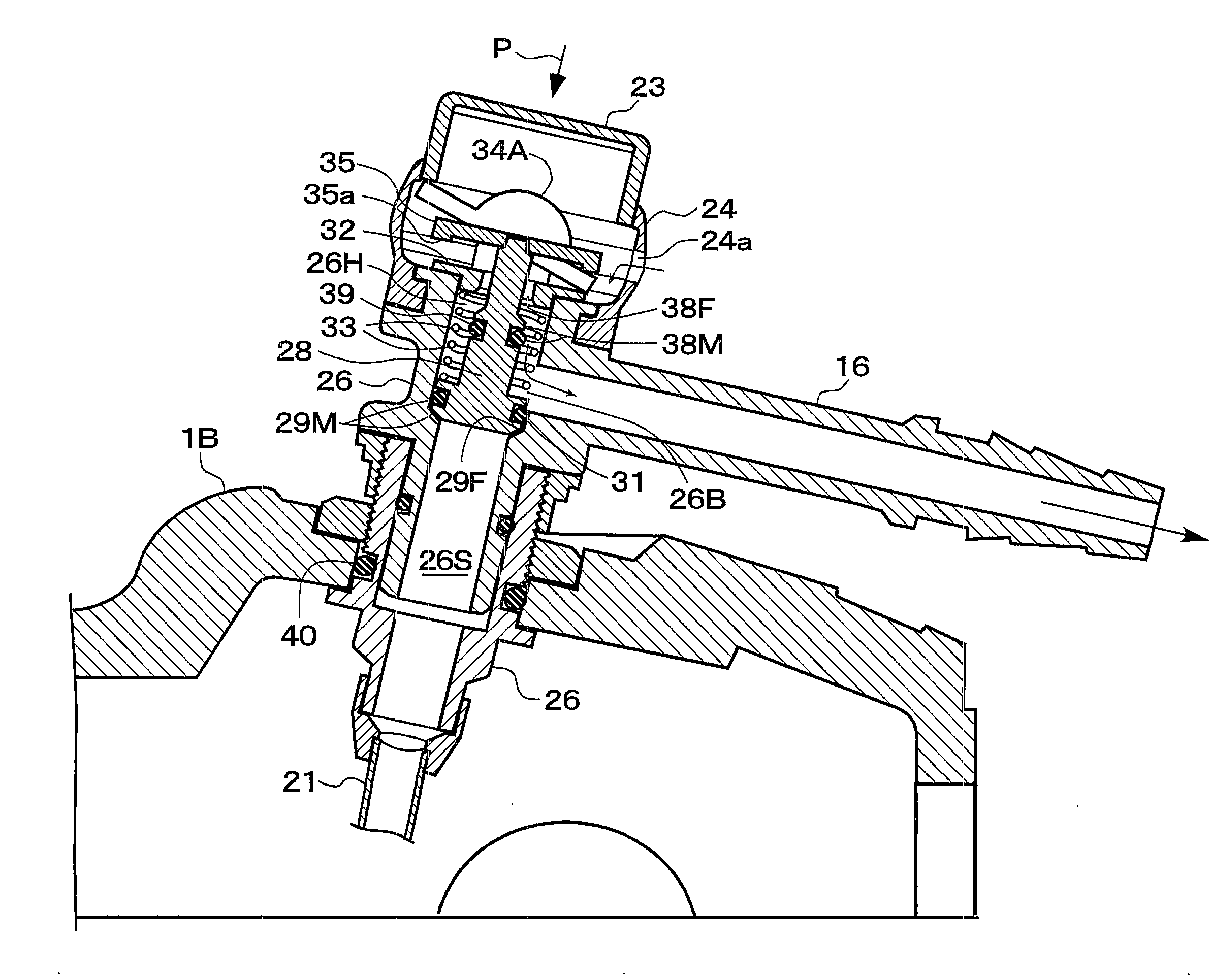
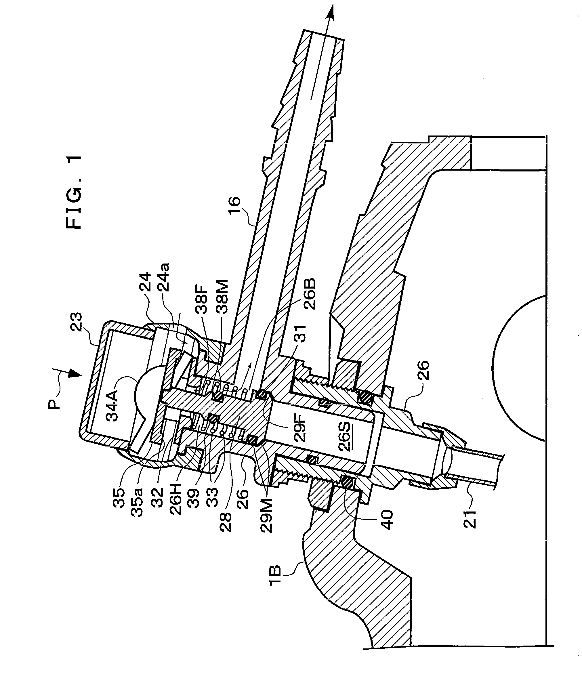
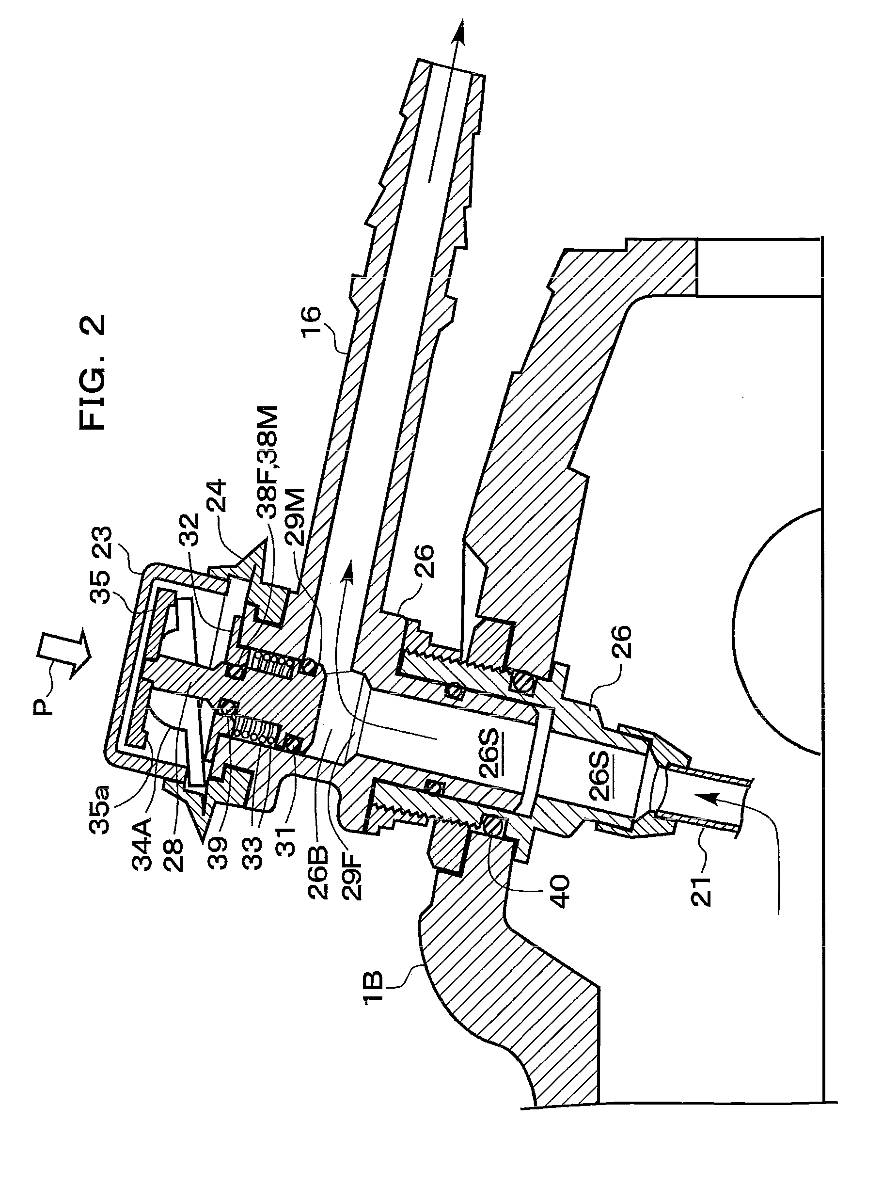
[0025]FIGS. 1 to 4 show a configuration of an endoscope sucking operation apparatus according to an embodiment, wherein FIGS. 1 and 2 are cross-sectional views of the sucking operation apparatus, FIG. 3 is an exploded view of the sucking operation apparatus, and FIG. 4 shows an entire configuration including a suction tank. As shown in FIG. 4, the sucking operation apparatus 15 according to the embodiment is applied to, e.g., a portable endoscope, the sucking operation apparatus 15 is arranged in an endoscope operating portion 1C, a suction connecting pipe 16 of this suction operating apparatus 15 is connected with a liquid storage tank 18 through a suction tube 17, and a suction pump is connected with this storage tank 18 via a suction tube 19. On the other hand, a suction tube 21 on an endoscope distal end side arranged in an endoscope operating portion 1B is connected with this suction operating apparatus 15.

[0026]As shown in FIGS. 1 to 3, in the sucking operation apparatus 15, a...


PUM


Abstract

When a suction button is pushed in a pushing operation direction, the suction button pushes down longer lever ends of inversion levers, shorter lever ends of the inversion levers are pushed up based on a seesaw operation and the principle of leverage, and a piston body coupled through a coupling body moves in a direction opposed to a pushing operation direction against an urging force of a spring in cooperation with this upward movement. As a result, a valve moving portion moves away from a valve receiving portion to open a suction duct valve portion and suction is carried out, but the piston body retires to an outer periphery side of a bent duct when the valve portion is opened, and hence a suction duct is widened, thereby facilitating suction of even, e.g., a fluid having high viscosity.

Description

[0001]The disclosure of Japanese Patent Applications No. 2008-213918, filed on Aug. 22, 2008, including its specification, claims and drawings, is incorporated herein by reference in its entirety.BACKGROUND OF THE INVENTION[0002]1. Field of the Invention[0003]The present invention relates to an endoscope sucking operation apparatus, and more particularly to a configuration of a sucking operation apparatus that moves a piston body from a valve portion to open a suction duct (conduit) by performing a pushing operation with respect to a suction button provided to an operating portion.[0004]2. Description of the Related Art[0005]FIG. 5 shows a configuration of a conventional endoscope apparatus, an endoscope has, e.g., a distal end portion 1A including an objective optical system, a solid-state image sensing device, and others, an operating portion 1B provided through a bending portion, and others, a forceps opening (a treatment instrument insertion channel introduction opening) 3 is pr...

Claims


Application Information

Patent Timeline
IPC IPC(8): A61B1/015
CPCA61B1/015A61B1/00068
Inventor YAMANE, KENJI
Owner FUJIFILM CORP
Why Eureka
Try Eureka