
Detection of a non-uniformly sampled sinusoidal signal and a doppler sensor utlizing the same

Inactive Publication Date: 2010-02-25
MITSUBISHI ELECTRIC CORP
View PDF1 Cites 10 Cited by
  • Summary
  • Abstract
  • Description
  • Claims
  • Application Information

AI Technical Summary

Benefits of technology

[0035]In a preferred embodiment of the invention, samples are analysed to determine the presence of a sinusoidal signal of frequency fx, the samples preferably being in the form of a pulse train. This pulse train may be the reflection from a moving object of a pulse train transmitted by a Doppler sensor. The timings of the samples are selected, in relation to the frequency fx, so that the averages of samples with such timings of sine and cosine waves of that frequency fx would be low, and preferably substantially zero. It is found that by choosing the timings in this manner, the effects of constant and slowly varying offsets, such as those resulting from stationary clutter, are suppressed.
[0056]is also significantly smaller than 1. As will be explained in the following, such a procedure results in a convenient form of a detection statistic, while providing a significant suppression of stationary clutter.
[0069]In an alternative arrangement involving transmission of pulses at random timings and dynamic selection of samples, the value Lx0 is calculated as each sample is received during an observation interval T0. When Lx0 has fallen below a predetermined threshold, and preferably after T0 has exceeded a predetermined minimum length, the observation interval is terminated. This arrangement can be modified by (a) discarding samples at the beginning of the observation interval as new samples are received, so that the observation interval maintains substantially the same length; and / or (b) discarding samples within the observation interval and thus using non-consecutive samples in a selective manner so as to reduce the clutter leakage more rapidly.
[0075]When the optimised timings are used, the discrete-time sine and cosine functions appearing in (5) will become ‘almost orthogonal’ to a constant function h(tk)≡1. This allows for effective suppression of a constant offset due to stationary clutter.
[0076]In accordance with another preferred feature of the invention, a further reduction of clutter leakage Lx0 is achieved by appropriate selection of the test frequency fx. That is, instead of selecting test frequencies which are (for example) regularly spaced, test frequencies which are slightly shifted from their nominal values are selected so that lower values of Lx0 can be obtained. If the introduced frequency offset |δfx| is smaller than 1 / T0, where T0 is the time interval used for signal processing, then the results obtained for the shifted test frequency can, with negligible error, be assumed to be correct for the nominal test frequency.
[0084]It should be pointed out that the above normalization will slightly reduce the effectiveness of clutter suppression, but the performance degradation will be negligible in practical applications.

Problems solved by technology

In such cases, conventional methods of frequency analysis will fail to provide reliable and statistically meaningful results.
Therefore, if conventional spectral analysis is employed to process non-uniformly sampled signals, the performance of such analysis will be degraded, and the results obtained unreliable.
However, the above Lomb periodogram method would not be capable of dealing in a statistically meaningful manner with a constant offset in the sample values.
This is regarded as a serious drawback of the method, because in some intended applications, a constant (or slowly-varying) offset will always be introduced by reflections of transmitted pulses from stationary clutter.
This problem would be particularly severe in a Doppler sensor intended to detect small moving objects in a heavy clutter environment.
However, despite the modifications made, this technique is also not well suited to detecting a non-uniformly sampled sinusoidal signal in a mixture of noise and stationary clutter.

Method used


Image

  • Detection of a non-uniformly sampled sinusoidal signal and a doppler sensor utlizing the same
  • Detection of a non-uniformly sampled sinusoidal signal and a doppler sensor utlizing the same
  • Detection of a non-uniformly sampled sinusoidal signal and a doppler sensor utlizing the same

Examples


Embodiment Construction

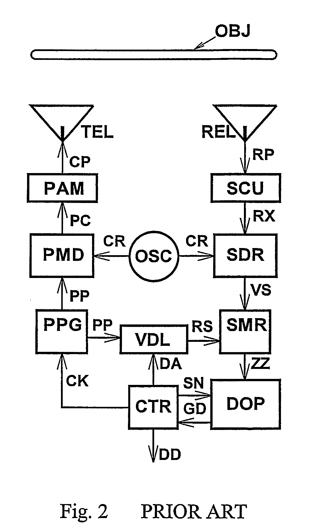
[0122]A Doppler sensor in accordance with the present invention is shown in FIG. 18 and corresponds with the prior art arrangement of FIG. 2 except as follows.

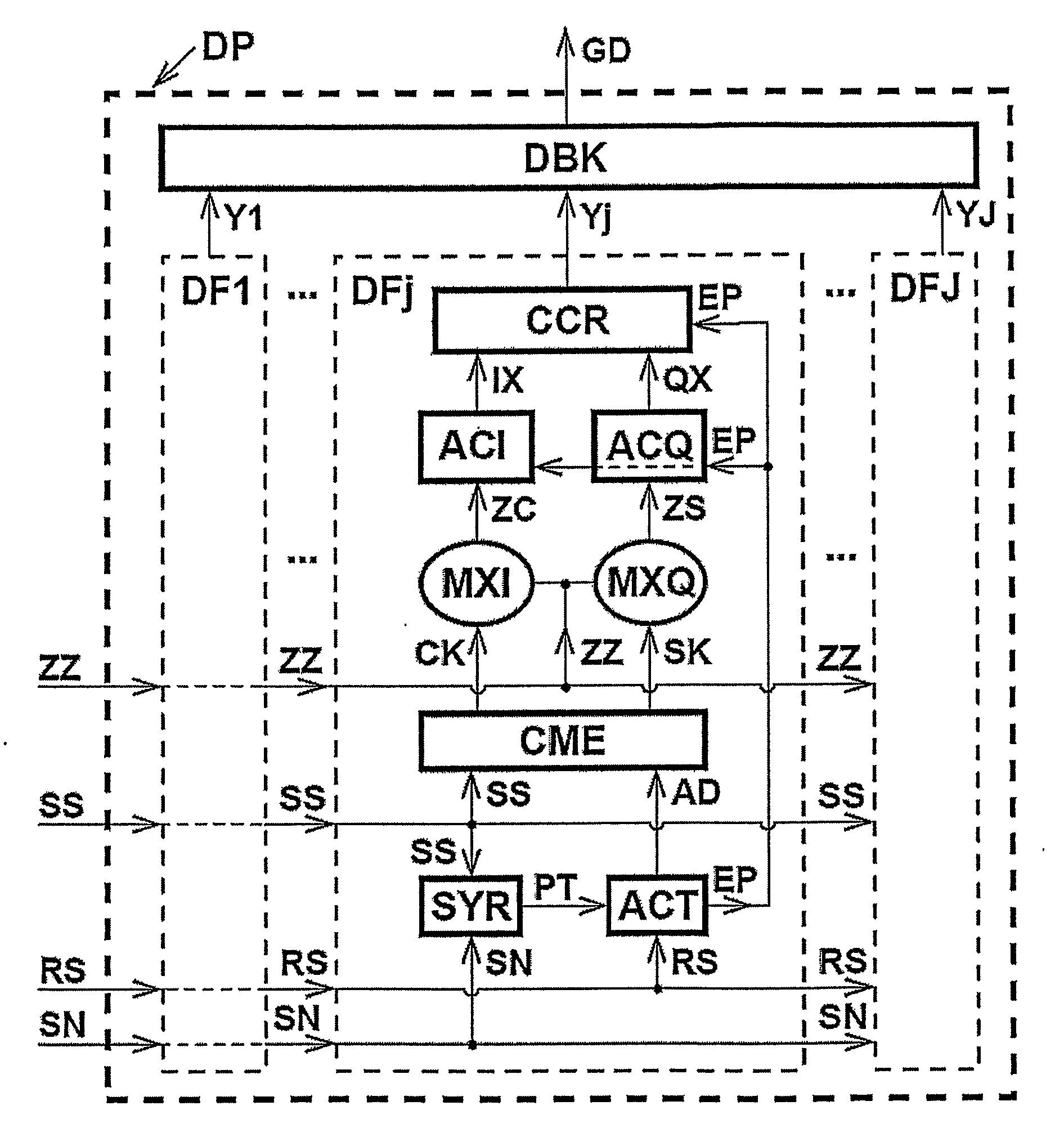
[0123]The pulse pattern generator PPG of FIG. 18 includes a cyclic difference set memory CDS and generates non-uniformly spaced pulses according to the technique described below. The Doppler processor DOP of FIG. 2 is replaced by a Doppler processor DP constructed in accordance with the present invention and shown in the functional block diagram of FIG. 9. Also, the control unit CTR generates additional signals, as explained further below.

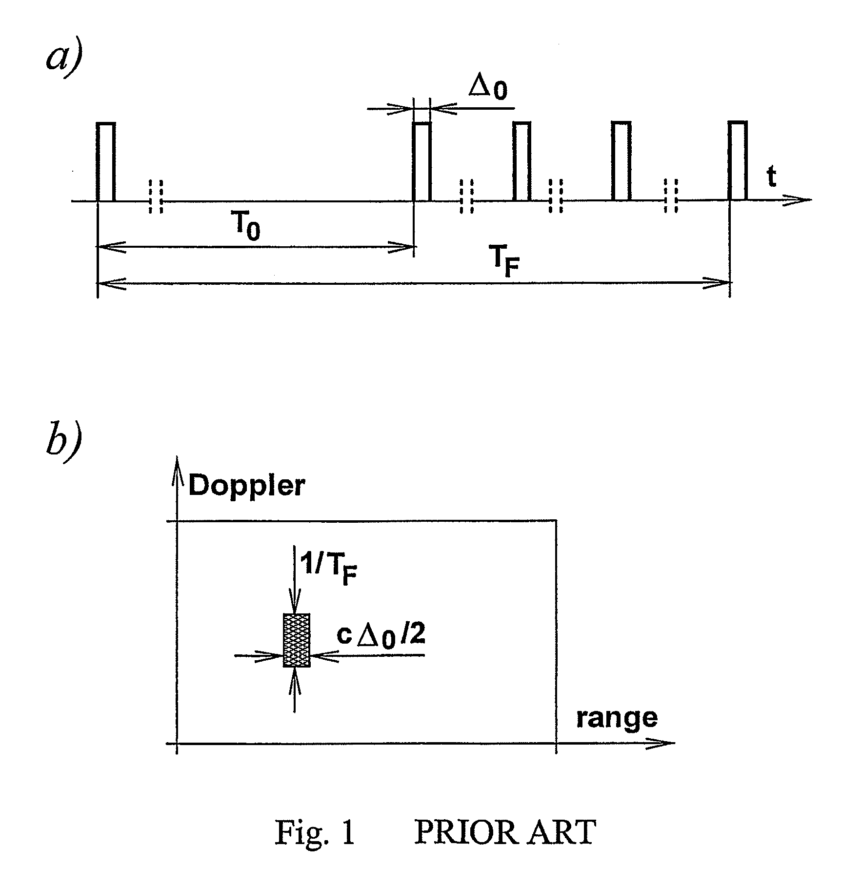
[0124]The pulse pattern generator PPG may, like the generator PPG of FIG. 2, be arranged to generate pulses in the pattern shown at s(t) in FIG. 4. As indicated above, the pulse train s(t) can be regarded as the combination, by interleaving, of K regular pulse trains.

[0125]However, in the arrangement of FIG. 18, the pulses in the composite pulse train s(t) are preferably staggered in such a w...


PUM


Abstract

A Doppler sensor operates by transmitting pulses at non-uniform intervals. Samples reflected by an object are processed by multiplying each one by first and second coefficients cxk and sxk, the products being separately summed to form two measures which are examined to determine whether an object exhibiting a particular Doppler frequency fx has been detected. The samples occur at non-uniformly spaced times txk such that the average of a cosine wave of frequency fx sampled at said times txk would be substantially zero and the average of a sine wave of frequency fx sampled at said times txk would be substantially zero.

Description

BACKGROUND OF THE INVENTION[0001]1. Field of the Invention[0002]This invention relates to a method employing non-uniform sampling to detect the presence of a sinusoidal signal with unknown frequency, phase and amplitude in noise and background clutter, the method being especially, but not exclusively, applicable to a sensor (e.g. a microwave sensor) utilizing a coherent pulsed electromagnetic transmission to determine both the range and Doppler frequency of an object of interest.[0003]2. Description of the Prior Art[0004]In many practical applications, there is a need to detect the presence of a sinusoidal signal with unknown frequency, phase and amplitude in background noise and clutter. Often, such detection is to be based on signal samples acquired at non-uniformly spaced time instants; additionally, the utilized average sampling rate may be substantially less than the Nyquist rate stipulated by sampling theorem. In such cases, conventional methods of frequency analysis will fail...

Claims


Application Information

Patent Timeline
IPC IPC(8): G06F15/00G01B21/16
CPCG01S7/35G01S7/02
Inventor SZAJNOWSKI, WIESLAW JERZY
Owner MITSUBISHI ELECTRIC CORP
Learn More