Locking device

Inactive Publication Date: 2010-03-04
AUSTCAST
View PDF11 Cites 9 Cited by
  • Summary
  • Abstract
  • Description
  • Claims
  • Application Information

AI Technical Summary

Benefits of technology

[0015]The way the locking portion(s) of the device can be selectively extended and retracted may at least help to overcome the need for hammers as described above. Indeed, when inserting the locking device of the present invention, the locking portion(s) (or possibly just one or some of the locking members if there are more than one) can be retracted so that the device can be easily inserted, generally by hand. This may be contrasted with prior arrangements such as the locking member in U.S. Pat. No. 659,305 in which the width between the lugs on the locking member impeded its insertion / retraction and therefore required a hammer to drive it in / out. Once the device of the present invention is inserted, it may be operated to extend the previously retracted locking portion(s) thereby securing the device in position. Conversely, when it is desired to replace a worn tooth point member, the device can be operated to retract the locking portion(s) allowing the device to be easily removed or slid back out, again, generally by hand. The worn tooth point member can then be removed and replaced.
[0016]Another possible benefit of the present invention may be that, because it may no longer be necessary to use hammers to drive a retaining pin or similar component into the apertures to secure the tooth point member to the adaptor, it may again be possible for the apertures in the adapter and the tooth point member to be oriented horizontally in use. This is because, at least with some possible embodiments of the invention, the amount of room needed to operate the extending and retracting means may be considerably less than the amount of room required to swing a hammer to drive the prior art retaining pins etc into the apertures. Therefore, with these embodiments, the amount of room between the teeth may be sufficient to allow easy insertion, retraction and operation of the locking device. Horizontal apertures may have the benefit of further reducing the risk of the locking device falling out, for example in the unlikely event of the locking device becoming damaged and not functioning properly.
[0018]Where the apertures in the adapter and the tooth point member are oriented horizontally, the apertures may be positioned such that the locking device is inserted along the neutral axis of the cross-section of the joined adapter+tooth point member (i.e. the cross-section taken through the adapter and tooth point member when the two are joined together). This may help to minimise the compressive and tensile stresses imposed on the locking device.
[0034]inserting a holding member into the registered apertures such that at least one protruding or recessed portion of the holding member engages with a recessed or protruding portion in one or both of the tooth point member or the adapter to prevent removal of the holding member from the apertures and
[0035]inserting a locking device into the apertures and then operating the locking device such that one or more locking portions extend to engage with one or both of the adapter or the tooth point member to prevent removal of the locking device from the apertures.

Problems solved by technology

In heavy industrial excavating equipment such as buckets used on draglines, loaders including front-end loaders, dippers, backhoes, shovels and other such large earthmoving machines, it is a common problem that the metal teeth on the leading edge(s) of the bucket become worn as the bucket is repeatedly forced through the ground during use.
This wear can eventually render the teeth ineffectual requiring the teeth, or at least the point or tip of each worn tooth, to be replaced.
One problem with these early assemblies was that, because the apertures were oriented vertically when the excavating equipment was in use, there was a danger that the pin could fall out allowing the tooth point member to fall off the adapter.
However, the assemblies where the apertures were oriented horizontally when the excavating equipment was in use were largely rejected by industry due to the difficulty in accessing the apertures.
Therefore, even though the amount of room between the tooth point members may have been enough for the pin to fit in between, the limited amount of room typically made it very difficult to swing a hammer to drive the pin in or out.
However, the need to use a hammer to insert and remove the locking member creates a significant workplace health and safety risk.
For example, there is a danger that a person's body part may be struck and seriously injured as a hammer is used to drive the locking member in and out.
Similarly, the act of wielding the hammer also has inherent potential to cause injury, such as back, shoulder or other muscle or joint injuries.

Method used


Image

  • Locking device
  • Locking device
  • Locking device

Examples


Embodiment Construction

)

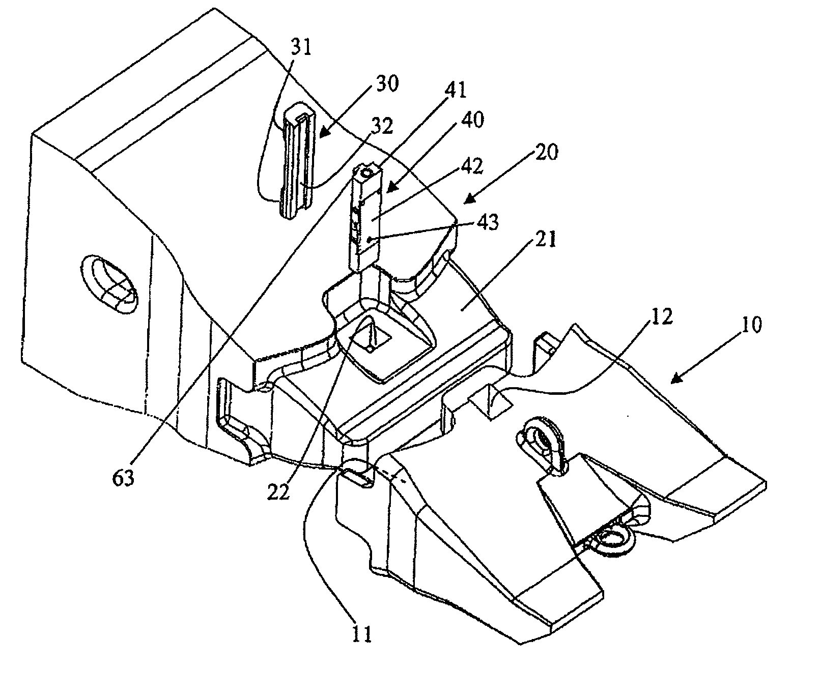
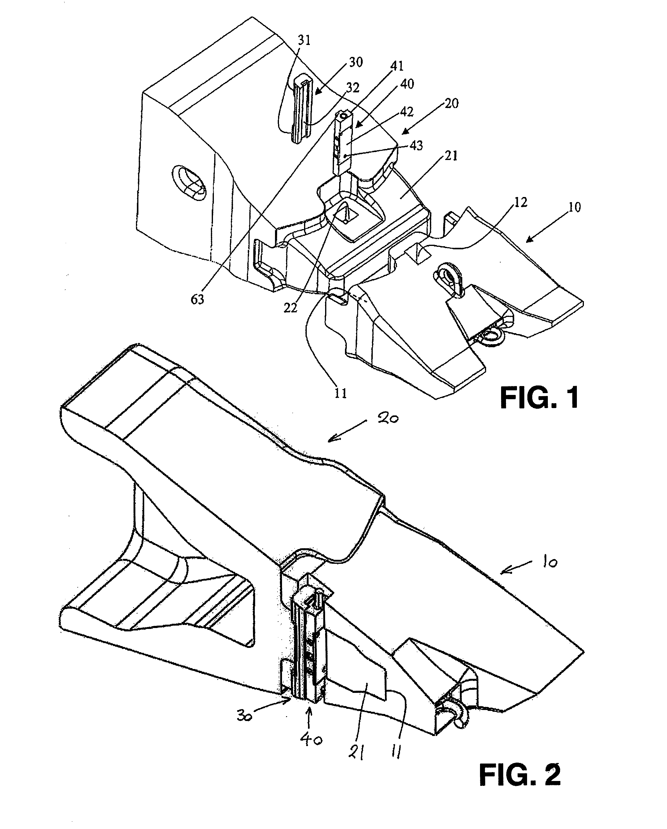
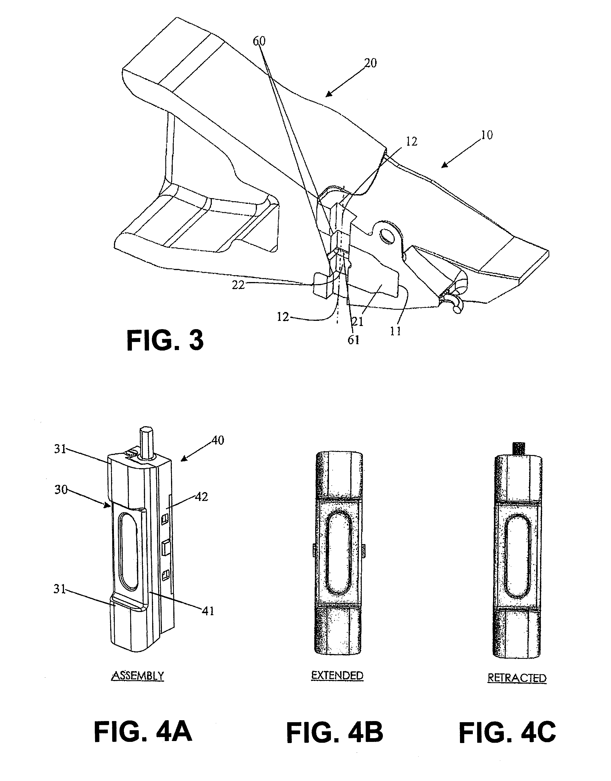
[0052]Referring first to FIGS. 1-3, it can be seen that the excavator tooth assembly comprises a tooth point member 10 (which will be referred to as the “tooth”) and an adapter 20. As shown in FIGS. 2 and 3, tooth 10 has a deep concave recess 11 defining a hollow rear end of the tooth. Adapter 20 has a forwardly protruding nose portion 21 whose shape corresponds to the internal shape of the recess 11 in the tooth. Hence, the tooth can be mounted on the adapter by sliding the hollow rear end of the tooth 10 onto the nose where it is snugly received as shown in FIGS. 2 and 3.

[0053]Also, from FIGS. 1-3 it can be seen that there is a square aperture 22 extending vertically through the full thickness of the nose 21 of the adapter. The tooth 10 also has a pair of corresponding square apertures 12 extending vertically through the thickness of the top and bottom walls of the tooth's hollowed out rear end. When the tooth 10 is slid onto the nose 21 of the adapter, the apertures 12 in the to...


PUM


Abstract

A locking device for use in securing a first part relative to a second part.

Description

BACKGROUND OF THE INVENTION[0001]1. Field of the Invention[0002]The present invention generally relates to a locking device for use in securing a first part relative to a second part.[0003]2. Description of Related Art[0004]In heavy industrial excavating equipment such as buckets used on draglines, loaders including front-end loaders, dippers, backhoes, shovels and other such large earthmoving machines, it is a common problem that the metal teeth on the leading edge(s) of the bucket become worn as the bucket is repeatedly forced through the ground during use. This wear can eventually render the teeth ineffectual requiring the teeth, or at least the point or tip of each worn tooth, to be replaced. Consequently, a number of assemblies have been developed where each tooth, or at least the point or tip thereof, can be replaced. For convenience, the prominent end or part of each excavator tooth that wears down during use and which can be replaced (typically the point or tip thereof) will...

Claims


Application Information

Patent Timeline
IPC IPC(8): A44B99/00B23P11/00
CPCE02F9/2841Y10T24/45686Y10T29/4995
Inventor RISSMAN, IAN
Owner AUSTCAST
Why Eureka
Try Eureka