Eureka AIR delivers breakthrough ideas for toughest innovation challenges, trusted by R&D personnel around the world.

Dryer System With Improved Throughput

a dryer and throughput technology, applied in the field of dryer systems, can solve the problems of elusive reliable consistent throughput of dryers, and achieve the effects of reducing the number of dryers, and optimizing the screen design

Inactive Publication Date: 2010-03-04
GALA INDUSTRIES INC
View PDF8 Cites 18 Cited by
  • Summary
  • Abstract
  • Description
  • Claims
  • Application Information

AI Technical Summary

Benefits of technology

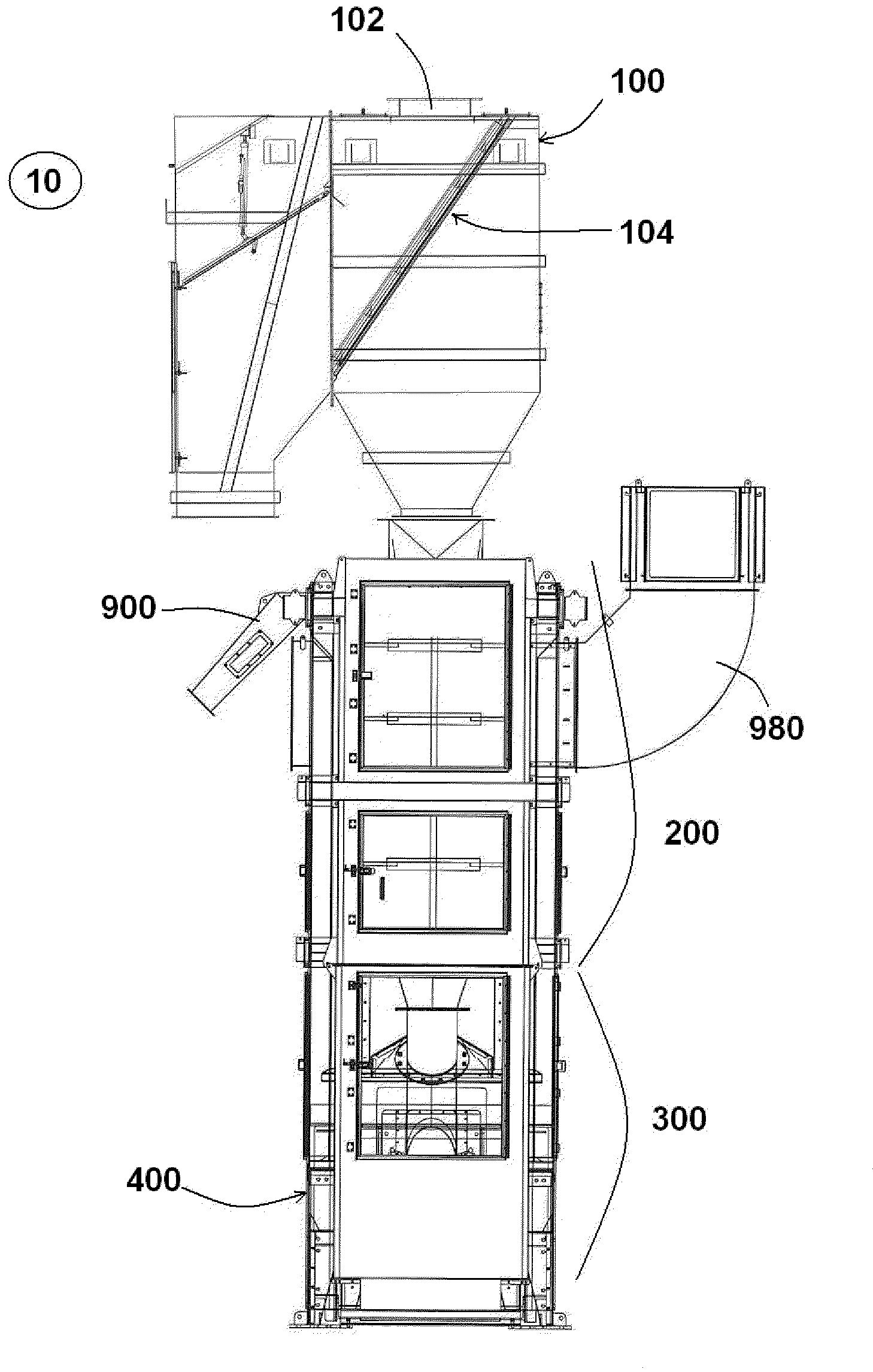
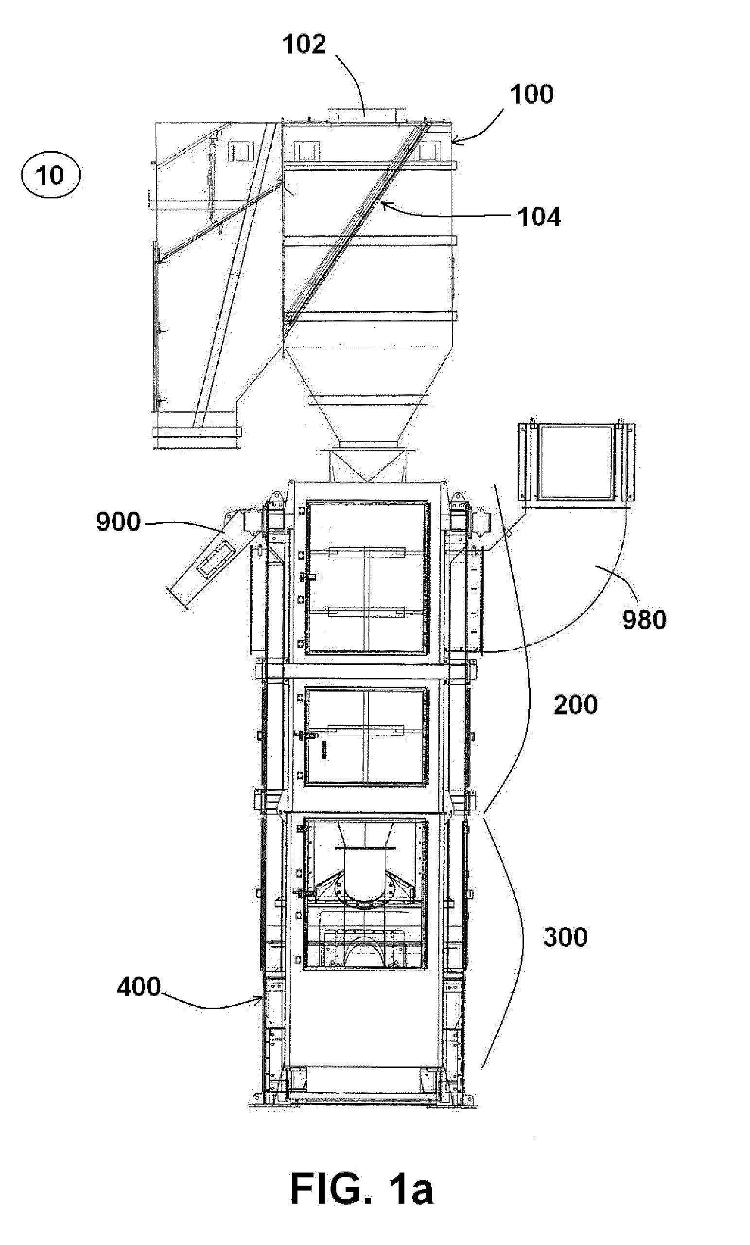
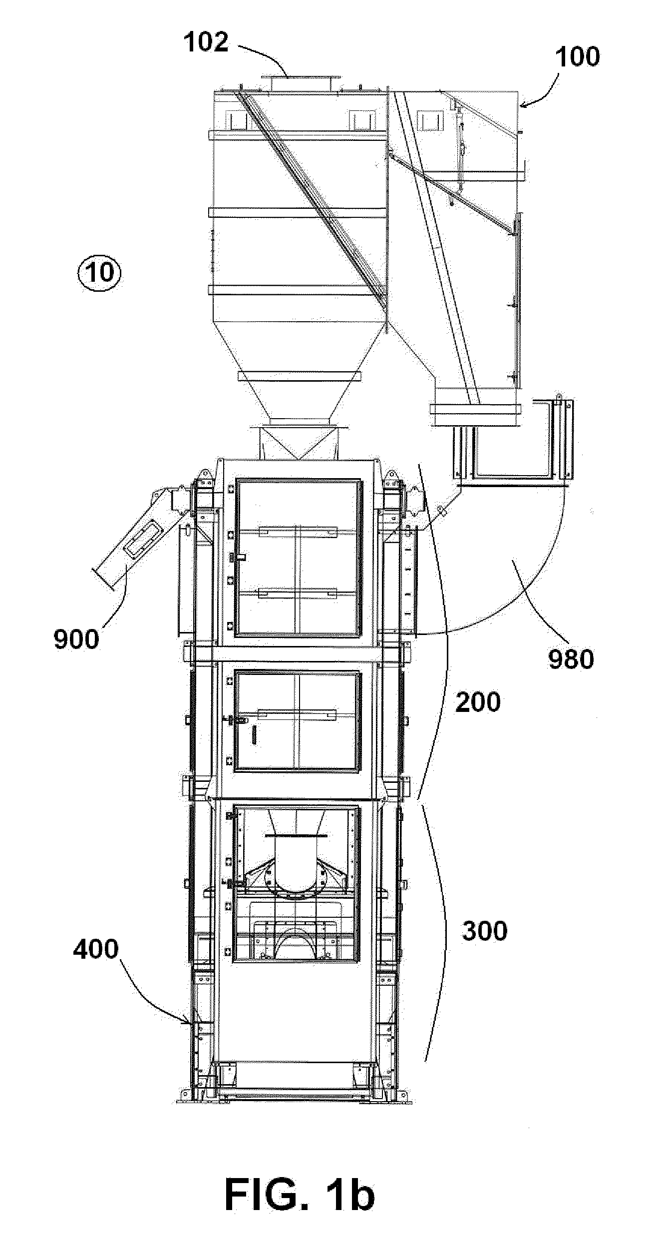
[0021]The agglomerate removal grid of the present invention preferably has an angle of inclination of greater than 50°, and permits passage of the slurry of particulates and fluid to the dewaterer, but collects agglomerated particulates of a size greater than the grid permits, and directs them toward an agglomerated particulate discharge chute. The grid is easily removable for cleaning, and for interchanging to adjust the size of the grid (and thus the size of the collected agglomerated particulates).
[0051]A still further object of the present invention is to provide a centrifugal dryer with an optimal screen design for efficiently separating pellets from transportation fluid.

Problems solved by technology

Surprisingly, with all these variants and attempts at dryer systems, a reliable consistent throughput dryer remains elusive, particularly one that has high throughput and low moisture content without compromising facile cleaning, manually or automatically, of an agglomerate catcher and without over-powering the dewatering components of the dryer.

Method used


Image

  • Dryer System With Improved Throughput
  • Dryer System With Improved Throughput
  • Dryer System With Improved Throughput

Examples


Embodiment Construction

[0103]Although preferred embodiments of the invention are explained in detail, it is to be understood that other embodiments are contemplated. Accordingly, it is not intended that the invention is limited in its scope to the details of construction and arrangement of components set forth in the following description or illustrated in the drawings. The invention is capable of other embodiments and of being practiced or carried out in various ways. Also, in describing the preferred embodiments, specific terminology will be resorted to for the sake of clarity.

[0104]It must also be noted that, as used in the specification and the appended claims, the singular forms “a,”“an” and “the” include plural referents unless the context clearly dictates otherwise. For example, reference to a pellet or lifter is intended also to include the processing of a plurality of pellets or lifters. References to a composition or fluid containing “an” ingredient or “a” constituent is intended to include othe...


PUM

PropertyMeasurementUnit
angle of inclinationaaaaaaaaaa
blade angleaaaaaaaaaa
angleaaaaaaaaaa

Abstract

A centrifugal dryer that has improved throughput capacity resulting from the combination of a high angle agglomerate catcher with optional overflow, increased dewatering capacity, a cylindrical dewatering feed chute, a modified rotor design with positionally and structurally modified lifters in the feed and dewatering section, the drying and propagating section, as well as the pellet discharge section, and an efficient circumferential foraminous membrane.

Description

BACKGROUND OF THE INVENTION[0001]1. Field of the Invention[0002]The present invention relates generally to a dryer system, and a method of drying, that has improved throughput capacity over conventional dryer systems, and more particularly to a dryer system combining a high angle agglomerate catcher with optional overflow, a cylindrical dewatering feed chute for increased dewatering capacity, and a centrifugal dryer with a modified rotor design with positionally and structurally modified lifters and an efficient circumferential foraminous membrane. The present invention increases pellet input and output rates while maintaining the ability to achieve desired pellet moisture content.[0003]2. Description of the Prior Art[0004]The generally independent processes and equipment in the extrusion, pelletization, and drying processes of polymeric material are known. Over time, the demand for dryer systems with high drying capacities has increased.[0005]Drying systems typically include both a...

Claims


Application Information

Patent Timeline
Patent Type & Authority Applications(United States)
IPC IPC(8): F26B17/30
CPCB29B9/16F26B17/24F26B5/08B29B13/00B29B13/06
Inventor AARON, CHARLES E.BOOTHE, DUANE A.LINKENHOKER, JOHN M.MORRIS, KERRY P.HANNAH, SAMUEL F.SMITH, WAYNE L.WENRICH, TOMAS C.
Owner GALA INDUSTRIES INC
Why Eureka
Eureka Blog
Learn More