Control system and method for braking a hydrostatic drive machine

a control system and drive machine technology, applied in the direction of braking systems, rotary clutches, fluid couplings, etc., can solve the problems of reducing the speed of the drive motor, adding weight and cost to the machine, wear and/or damage to the components of the drive system,

Active Publication Date: 2010-03-04
CATERPILLAR INC
View PDF28 Cites 28 Cited by
  • Summary
  • Abstract
  • Description
  • Claims
  • Application Information

AI Technical Summary

Benefits of technology

[0005]In one aspect, a method of braking a hydrostatic drive machine includes steps of reducing a displacement of a pump of a hydrostatic drive system to a non-zero displacement, and increasing a displacement of a motor of the hydrostatic drive system to a displacement that is less than a maximum displacement. The method also includes a step of accelerating an engine of the hydrostatic drive system toward a desired engine speed range.
[0006]In another aspect, a hydrostatic drive machine includes an internal combustion engine, at least one variable displacement pump mechanically coupled to the internal combustion engine, and at least one variable displacement motor fluidly coupled to the variable displacement pump. The variable displacement motor is mechanically coupled to at least one ground engaging element of the hydrostatic drive machine. An electronic controller is in communication with the variable displacement pump and the variable displacement motor and, according to an exemplary embodiment, is configured to receive a machine braking request. The electronic controller is further configured to issue a pump displacement command to reduce a displacement of the variable displacement pump to a non-zero displacement, and issue a motor displacement command to increase a di

Problems solved by technology

Utilizing such brakes, however, may cause wear and/or damage to components of the drive system and, additionally, may add weight and cost to the machine.
The latter se

Method used


Image

  • Control system and method for braking a hydrostatic drive machine
  • Control system and method for braking a hydrostatic drive machine
  • Control system and method for braking a hydrostatic drive machine

Examples


Embodiment Construction

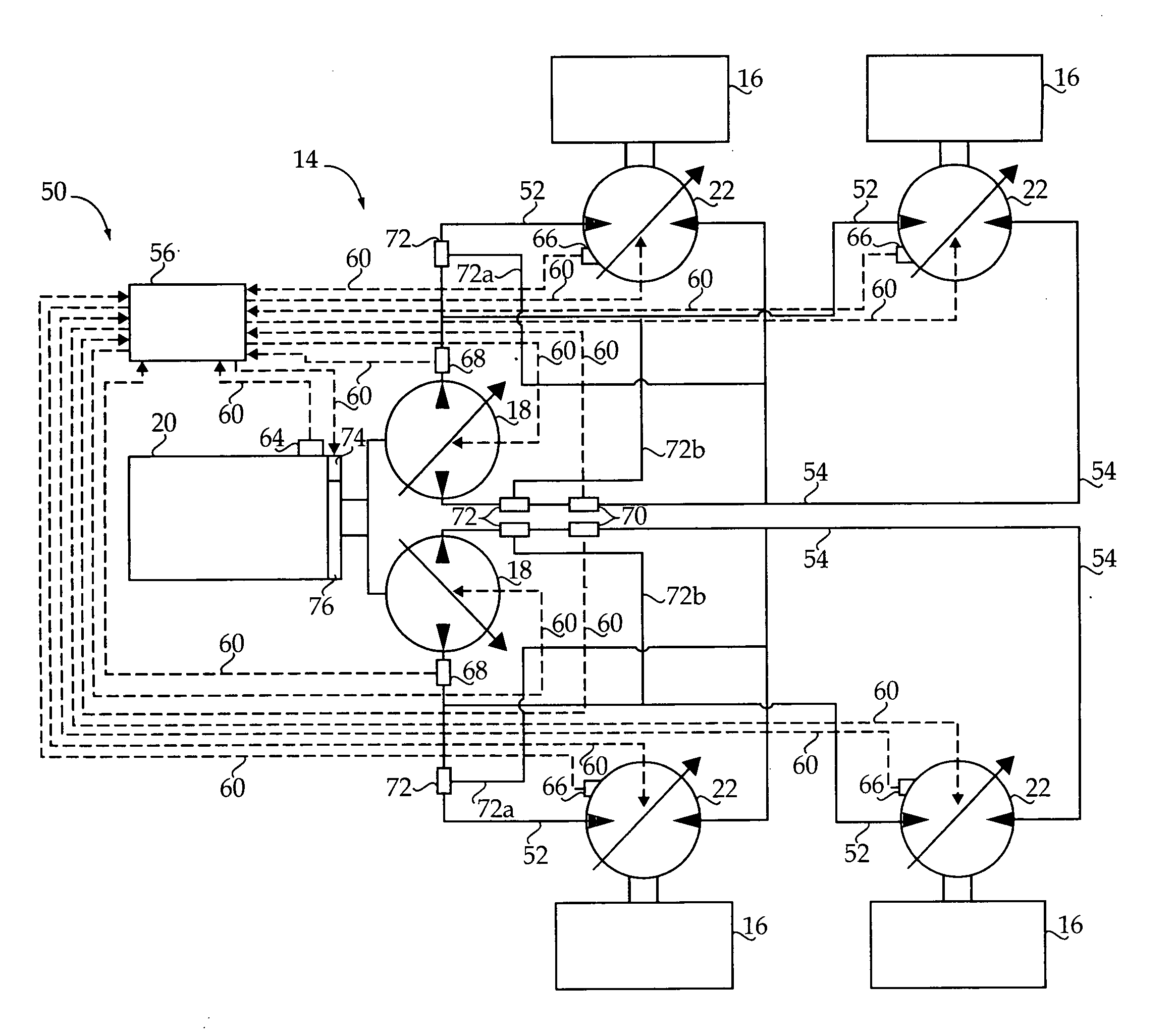
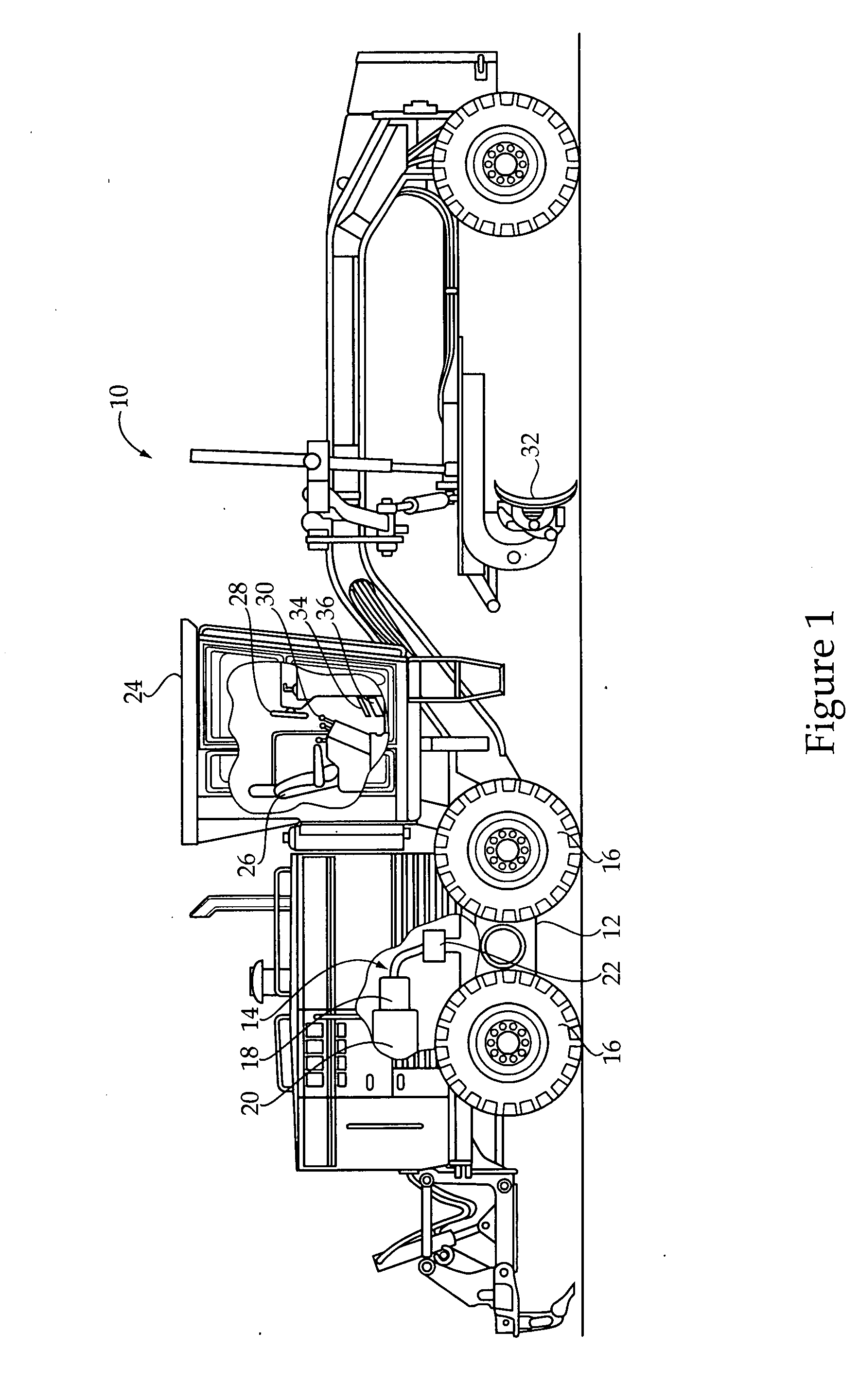
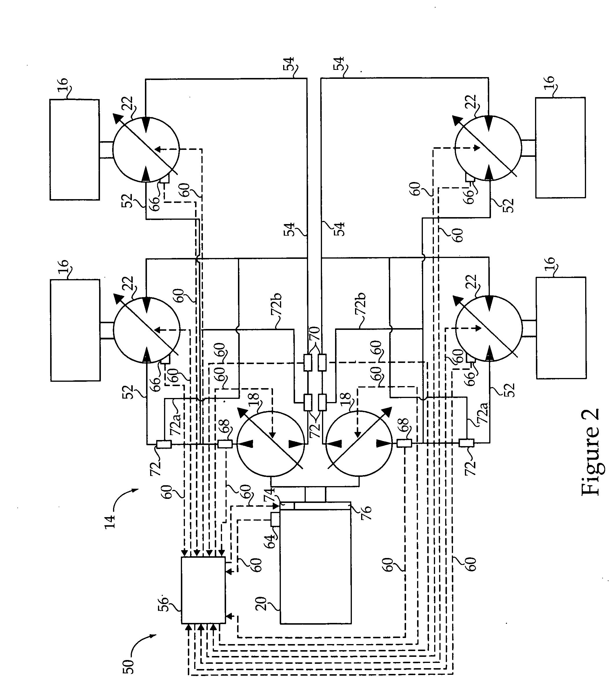
[0011]An exemplary embodiment of a machine 10 is shown generally in FIG. 1. The machine 10 may be a motor grader, as shown, or any other off-highway or on-highway vehicle having a hydrostatic drive system. As such, machine 10 may also be referenced herein as a hydrostatic drive machine or, more specifically, a hydrostatic drive motor grader. In the illustrated embodiment, machine 10 generally includes a frame 12 having a hydrostatic drive system 14 supported thereon for driving ground engaging elements 16, such as tracks or wheels (shown), of the machine 10. A strategy presented herein for controlling the hydrostatic drive system 14 may be widely applicable to any hydrostatic drive machine and, therefore, it should be appreciated that the specific embodiments provided are presented for exemplary purposes only.

[0012]The hydrostatic drive system 14 may generally include at least one pump 18, such as a hydraulic pump, driven by a prime mover, such as a compression or spark-ignited inte...


PUM


Abstract

A method of braking a hydrostatic drive machine includes steps of reducing a displacement of a pump of a hydrostatic drive system to a non-zero displacement, and increasing a displacement of a motor of the hydrostatic drive system to a displacement that is less than a maximum displacement. The method also includes a step of accelerating an engine of the hydrostatic drive system toward a desired engine speed range.

Description

TECHNICAL FIELD[0001]The present disclosure relates generally to a control system and method for a hydrostatic drive machine, and more particularly to a control system and method for braking the hydrostatic drive machine.BACKGROUND[0002]Many machines, including large off-highway machines, are known to use hydrostatic drive systems to drive the ground engaging elements, such as wheels or tracks, of the machine. Such hydrostatic drive system commonly includes at least one pump driven by a prime mover, such as an internal combustion engine, of the machine. The pump may be configured to drive one or more sets of motors, which, in turn, power the ground engaging elements of the machine. The pump, and / or motors, may provide variable displacement, such that a fluid flow between the components of the hydrostatic drive system may be adjusted while the machine is running. As a result, direction, speed, and torque of the drive wheels may be continuously varied.[0003]These machines typically in...

Claims


Application Information

Patent Timeline
IPC IPC(8): B60T10/04B60T1/08B60W30/18
CPCB60T10/04B60W10/06B60W10/103B60W30/18109B60W30/18136F16H61/465B60Y2200/411F16H61/4157F16H61/421F16H61/431B60W2710/0644
Inventor BASANA, J. SWAPNADANIEL, STEVEN A.THOMSON, NORVALANDERSON, MICHAELSERGISON, DANIEL P.
Owner CATERPILLAR INC
Why Eureka
Try Eureka