Linear solar energy collection system with secondary and tertiary reflectors

a solar energy and solar collector technology, applied in the direction of solar heat collector mounting/support, solar heat collector safety, light and heating apparatus, etc., can solve the problems of difficult installation, heavy mirrors, and poor efficiency of solar collector types described above, so as to reduce the effect, increase efficiency, and improve efficiency

Inactive Publication Date: 2010-03-04
ARXIEL CLEAN TECH
View PDF16 Cites 25 Cited by
  • Summary
  • Abstract
  • Description
  • Claims
  • Application Information

AI Technical Summary

Benefits of technology

[0007]This invention is directed to a linear solar energy collection system that improves solar field efficiency, lowers operational and maintenance costs, and therefore reduces the overall cost of generating electricity per kilowatt-hour.
[0008]One aspect of this invention is predicated on the concept of providing a simple, modular linear solar energy collection system comprising one or more reflector units each fabricated using light-weight materials arranged in a construction that is highly accessible, easily maintained, and lower in initial cost. In one embodiment, each reflector unit includes a light-weight, generally planar aluminum frame that mounts a number of solar panels in a fixed position at angles progressively increasing from the frame centerline outwardly to its perimeter so as to collectively form a surface having a shape approximating that of a parabola. The focal line of such parabola is coincident with a secondary reflector which receives sunlight incident on the solar panels and reflects such light onto a receiver tube mounted in a fixed position substantially concentric to the centerline of the frame. The frame is supported by truss elements to add rigidity, and is connected to a drive mechanism operative to pivot the frame and truss elements in order to track the position of the sun during the course of a day. A number of individual reflector units may be arranged side-by-side to form a solar energy collection system having a collection field of desired size.
[0010]Still another embodiment of this invention is designed to increase efficiency by reducing the effects that the secondary reflector in the previously described embodiments can have due to blockage of incident sunlight. It has been found that a portion of the sunlight directed to each reflector unit is blocked by the secondary reflector and does not reach the solar panels, and, in turn, the receiver tube. In this embodiment, at least one other secondary reflector is provided in between the first secondary reflector and the receiver tube as well as at least one tertiary reflector. As described below, the secondary reflectors and tertiary reflector(s) cooperate with the solar panels to direct sunlight onto the receiver tube at a higher efficiency.
[0011]In all of the embodiments of this invention, each solar panel preferably comprises a honeycomb aluminum section and a highly reflective silver-metallized surface connected together by an adhesive layer. The solar panels are strong, durable, light-weight and efficiently reflect incident sunlight many times its normal intensity onto the secondary reflector. The reflective surface of such panels may be washed to maintain cleanliness, which, in one presently preferred embodiment of this invention, is accomplished by the provision of an in-ground washing system operative to direct cleansing water against such surfaces.
[0012]A heat transfer fluid is circulated through the receiver tube for heating by the sunlight directed thereto from the secondary reflector. Because the receiver tube is fixed relative to the pivoting frame, it may be connected to a fixed transfer conduit that communicates with a steam generator and turbine. Since both the receiver tube and transfer conduit are mounted in a fixed position, heat losses resulting from the transfer of fluid out of the receiver tube are minimized and maintenance problems with the moving connections between the receiver tube and transfer conduit that were required in prior art systems, as described above, are substantially eliminated.

Problems solved by technology

Solar collection systems of the type described above suffer from a number of deficiencies.
These mirrors are very heavy, and are available from only a few manufacturers.
They are difficult to install and require robust mounting structure to support in order to provide for accurate positioning of the reflective surface 12 and to resist wind loads.
While thinner glass mirrors have been suggested as an alternative, they are more fragile resulting in increased handling costs and breakage losses.
Most support structures 18 for the mirrors are formed of galvanized steel which is also heavy, requires precise manufacturing and is expensive to build.
Bridge trusses have been employed in more recent designs for the support structures 18, but have proven to be nearly equally expensive to manufacture and often are lacking in torsional stiffness.

Method used


Image

  • Linear solar energy collection system with secondary and tertiary reflectors
  • Linear solar energy collection system with secondary and tertiary reflectors
  • Linear solar energy collection system with secondary and tertiary reflectors

Examples


Embodiment Construction

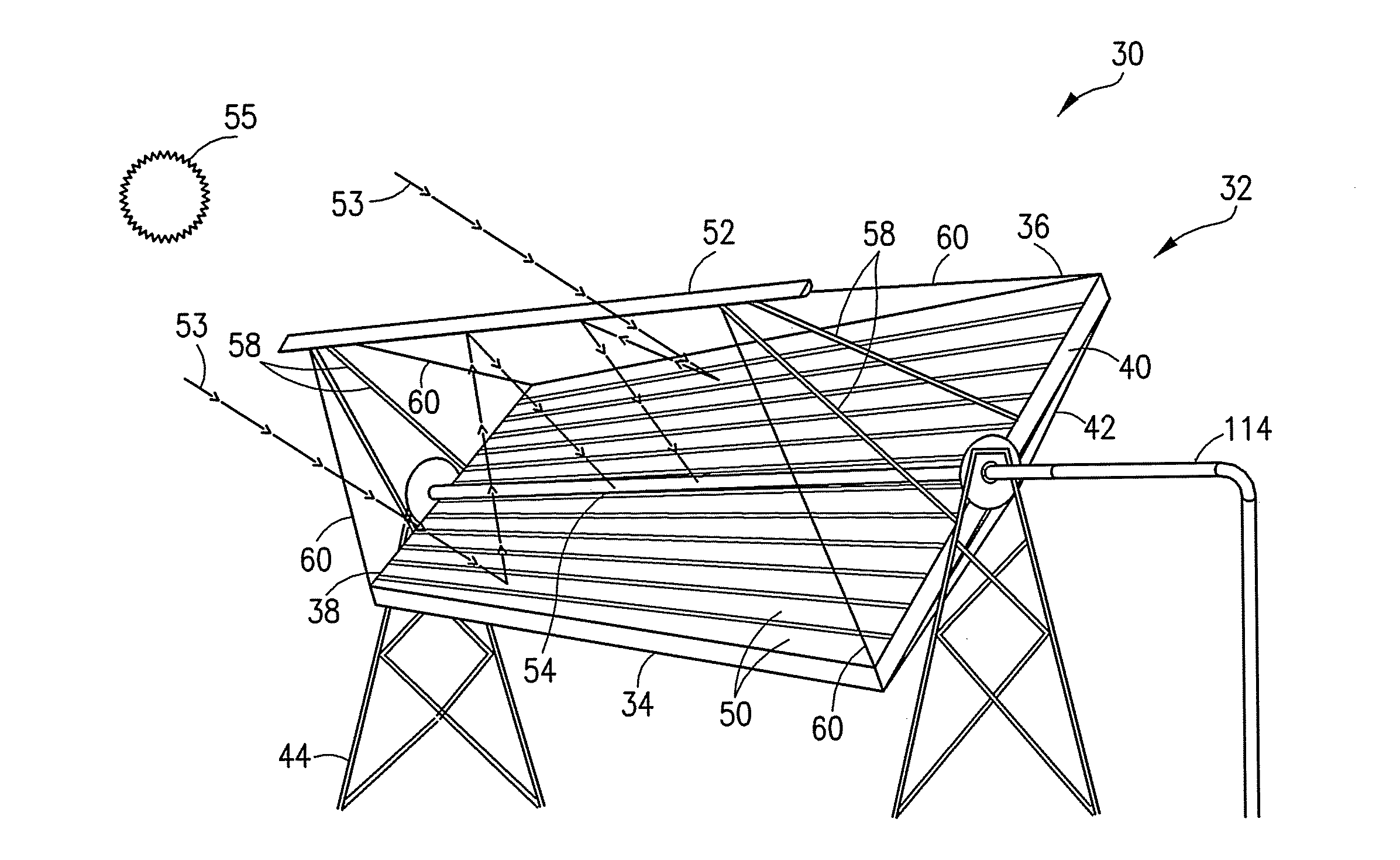
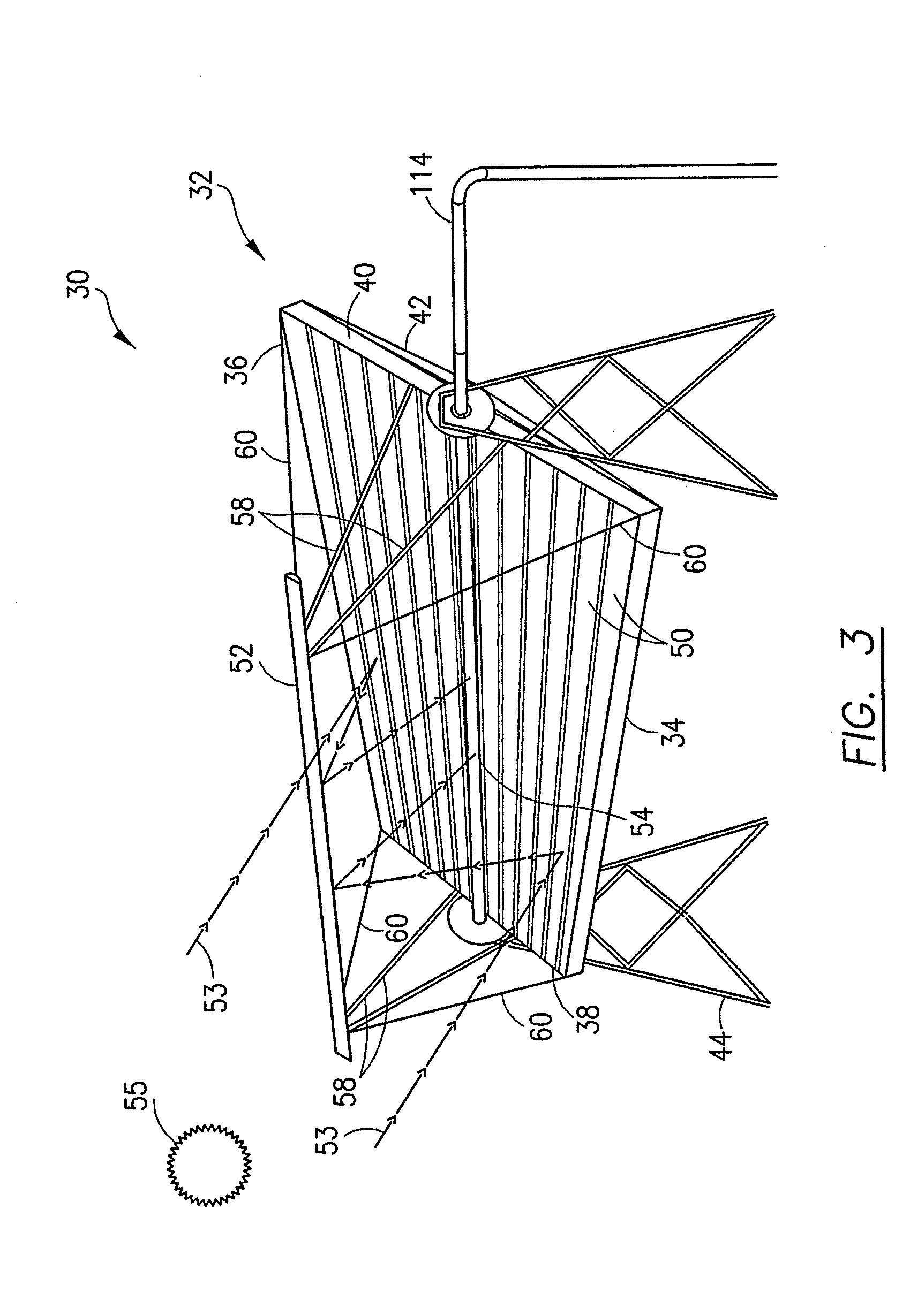
[0031]Referring now to FIGS. 3-12, one embodiment of a solar energy collection system according to this invention is illustrated which may comprise several individual reflector units 30 oriented side-by-side, as discussed below with reference to FIG. 12. The reflector unit 30 is initially generally described, followed by a discussion of individual aspects of the design.

[0032]The reflector unit 30 includes a frame 32 having opposed side walls 34, 36, and opposed end walls 38, 40 connected together in a generally rectangular shape as depicted in FIG. 3. The walls 34-40 are preferably formed of aluminum or other light-weight, weather resistant and durable material. The frame 32 is reinforced by a truss structure 42, a portion of which is shown in FIGS. 3 and 12, which is also preferably formed of aluminum or similar material. The truss structure 42 and frame 32 may be supported above ground level by pylons 44 secured on a foundation such as concrete footers (not shown) that can support...


PUM


Abstract

A modular linear solar energy collection system comprises one or more reflector units each having a light-weight generally planar aluminum frame that mounts a number of solar panels in a fixed position at angles which progressively increase from the frame centerline outwardly to its perimeter so as to collectively form a surface having a shape approximating that of a parabola. Sunlight incident on the solar panels is reflected by a combination of secondary and tertiary reflectors onto a receiver tube mounted in a fixed position concentric to the centerline of the frame. The frame is connected to a drive mechanism operative to pivot the frame and solar panels in order to track the position of the sun during the course of a day.

Description

CROSS-REFERENCE TO RELATED APPLICATIONS[0001]This application is a continuation-in-part of U.S. application Ser. No. 12 / 198,219, filed Aug. 26, 2008 and entitled “Linear Solar Energy Collection System.”FIELD OF THE INVENTION[0002]This invention relates to the generation of electrical energy through solar thermal power collection, and, more particularly, to a linear solar energy collection system that employs an array of light-weight solar panels, secondary reflectors, tertiary reflectors and a fixed linear receiver tube in which a heat transfer fluid is circulated.BACKGROUND OF THE INVENTION[0003]Systems for the generation of electricity by collecting solar thermal radiation were first introduced in 1914, and have become increasingly popular with the rise in fossil fuel costs and concerns over global warming. The majority of solar energy collection systems currently in use are of the type depicted in FIGS. 1 and 2. A generally parabolic-shaped trough 10 is provided having a curved, ...

Claims


Application Information

Patent Timeline
Patent Type & Authority Applications(United States)
IPC IPC(8): F24J2/10F24S23/70
CPCF24J2/055Y02E10/47F24J2/1057F24J2/14F24J2/18F24J2/4607F24J2/541F24J2/5424F24J2002/1076F24J2002/108F24J2002/5286F24J2002/5458F24J2002/5465F24J2002/5482Y02E10/41Y02E10/44Y02E10/45F24J2/07F24S10/45F24S20/20F24S23/74F24S23/79F24S23/82F24S30/425F24S30/455F24S40/00F24S80/30F24S2023/87F24S2023/872F24S2025/017F24S2030/133F24S2030/135F24S2030/15Y02E10/40
Inventor AMMAR, DANNY F.DREWES, JONATHAN
Owner ARXIEL CLEAN TECH
Why Eureka
Try Eureka