Control apparatus and control method for hybrid vehicle

a control apparatus and hybrid technology, applied in the direction of battery/fuel cell control arrangement, electric devices, gearing, etc., can solve the problems of easy problem, etc., and achieve the effect of preventing overcurrent and/or overcurrent at the power storage devi

a control apparatus and hybrid technology, applied in the direction of battery/fuel cell control arrangement, electric devices, gearing, etc., can solve the problems of easy problem, etc., and achieve the effect of preventing overcurrent and/or overcurrent at the power storage devi

US20100051367A1Active Publication Date: 2010-03-04TOYOTA JIDOSHA KK +1

Image

  • Control apparatus and control method for hybrid vehicle
  • Control apparatus and control method for hybrid vehicle
  • Control apparatus and control method for hybrid vehicle

Examples


Embodiment Construction

[0034]Embodiments of the present invention will be described hereinafter in detail. In the drawings, the same or corresponding elements have the same reference characters allotted, and description thereof will not be generally repeated.

[0035](Configuration of Hybrid Vehicle)

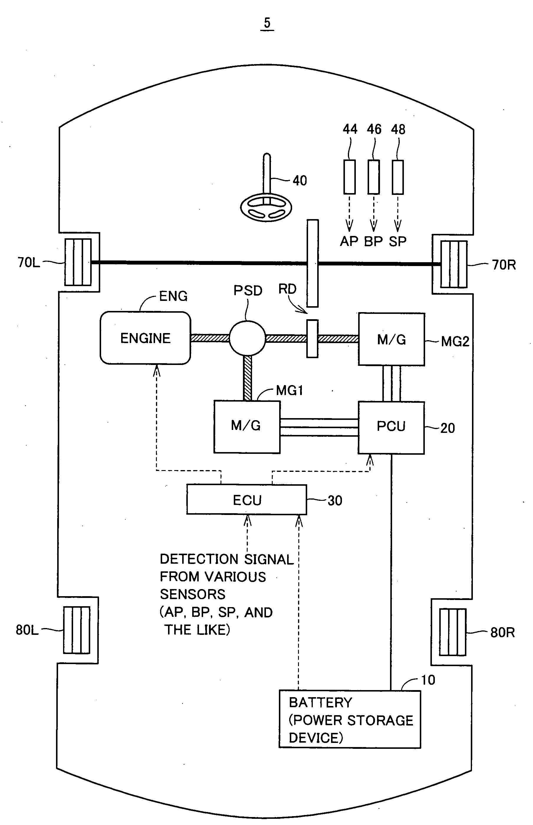
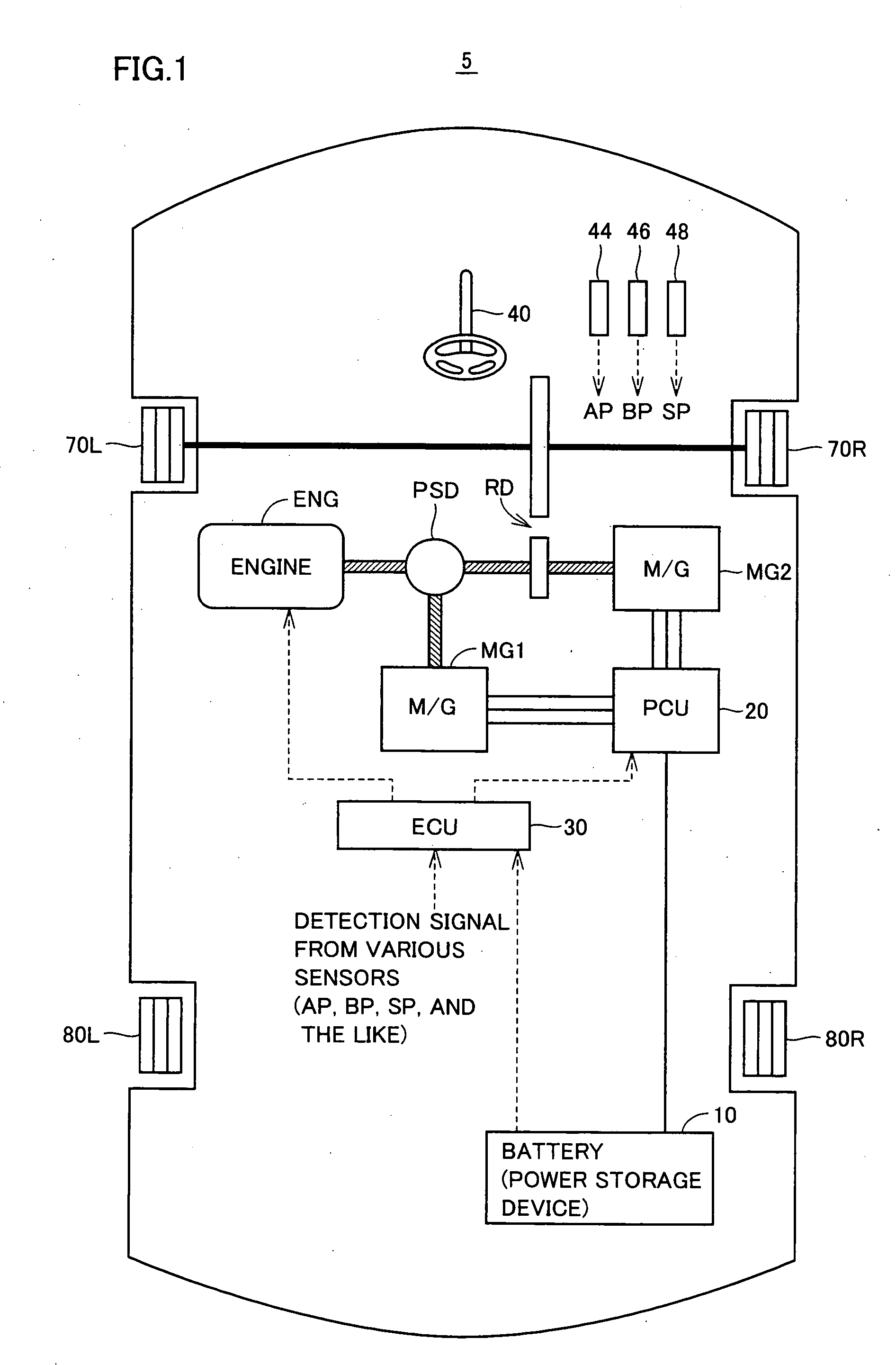
[0036]FIG. 1 is a schematic block diagram representing an entire configuration of a hybrid vehicle in which a control apparatus of the present invention is incorporated.

[0037]Referring to FIG. 1, a hybrid vehicle 5 includes an engine ENG, motor generators MG1 and MG2, a battery 10, a power conversion unit (PCU: Power Control Unit) 20, a power split device PSD, a reduction gear RD, front wheels 70L and 70R, rear wheels 80L and 80R, and an electronic control unit (ECU) 30. The control apparatus according to the present embodiment is realized by a program executed by ECU 30, for example. Although FIG. 1 represents hybrid vehicle 5 with front wheels 70L and 70R as driving wheels, rear wheels 80L and 80R may be employ...


PUM


Abstract

The present invention is directed to solve the problem of generation of overdischarging from a power storage device according to compensation for reduction in electrical power generated by an MG1 corresponding to reduction in the revolution speed of the MG1. When detection is made of reduction in the revolution speed of the MG1 corresponding to reduction in the engine speed, any of the four following operations is carried out: (1) modifying the output torque of the MG1 such that electrical power generated by the MG1 increases; (2) modifying the output torque of an MG2 such that power consumption by the MG2 is reduced; (3) forcing the control mode of the MG1 to be changed to PWM control from one-pulse switching control; and (4) reducing the DC voltage command value for the converter.

Description

TECHNICAL FIELD[0001]The present invention relates to a control apparatus and control method for a hybrid vehicle. More particularly, the present invention relates to control for a hybrid vehicle including an engine, and a motor generator connected to the engine via a power split device.BACKGROUND ART[0002]There is conventionally proposed a hybrid vehicle incorporating an engine and first and second rotating electric machines (motor generator). For example, Japanese Patent Laying-Open No. 10-238380 discloses a hybrid vehicle incorporating an engine, a first rotating electric machine (motor generator), connected to the engine to determine the engine speed, and a second rotating electric machine (motor generator) to determine the driving force of the vehicle.[0003]Particularly, Japanese Patent Laying-Open No. 10-238380 discloses a control apparatus for improving the engine response by setting appropriately the torque command value of the first and second motor generators during transi...

Claims


Application Information

Patent Timeline
04 Mar 2010
Publication
US20100051367A1
IPC
B60W20/00; B60L50/16
CPC
B60K6/445; Y02T10/70; B60L11/1861; B60L2240/421; B60L2240/423; B60W10/08; B60W10/26; B60W20/00
Inventors
YAMADA, KENJI; ITOH, TAKESHI