
Seat assembly for a vehicle

a vehicle and seat technology, applied in the field of seats for vehicles, can solve the problems of unbelted occupants that are typically uncontrollable under their own momentum, lose the benefits of the compartmentalized seating required by fmvss 222 for school buses, and the back cannot be controlled. , to achieve the effect of quick and easy assembly and preventing rotation

Inactive Publication Date: 2010-03-04
SYNTEC SEATING SOLUTIONS
View PDF92 Cites 26 Cited by
  • Summary
  • Abstract
  • Description
  • Claims
  • Application Information

AI Technical Summary

Benefits of technology

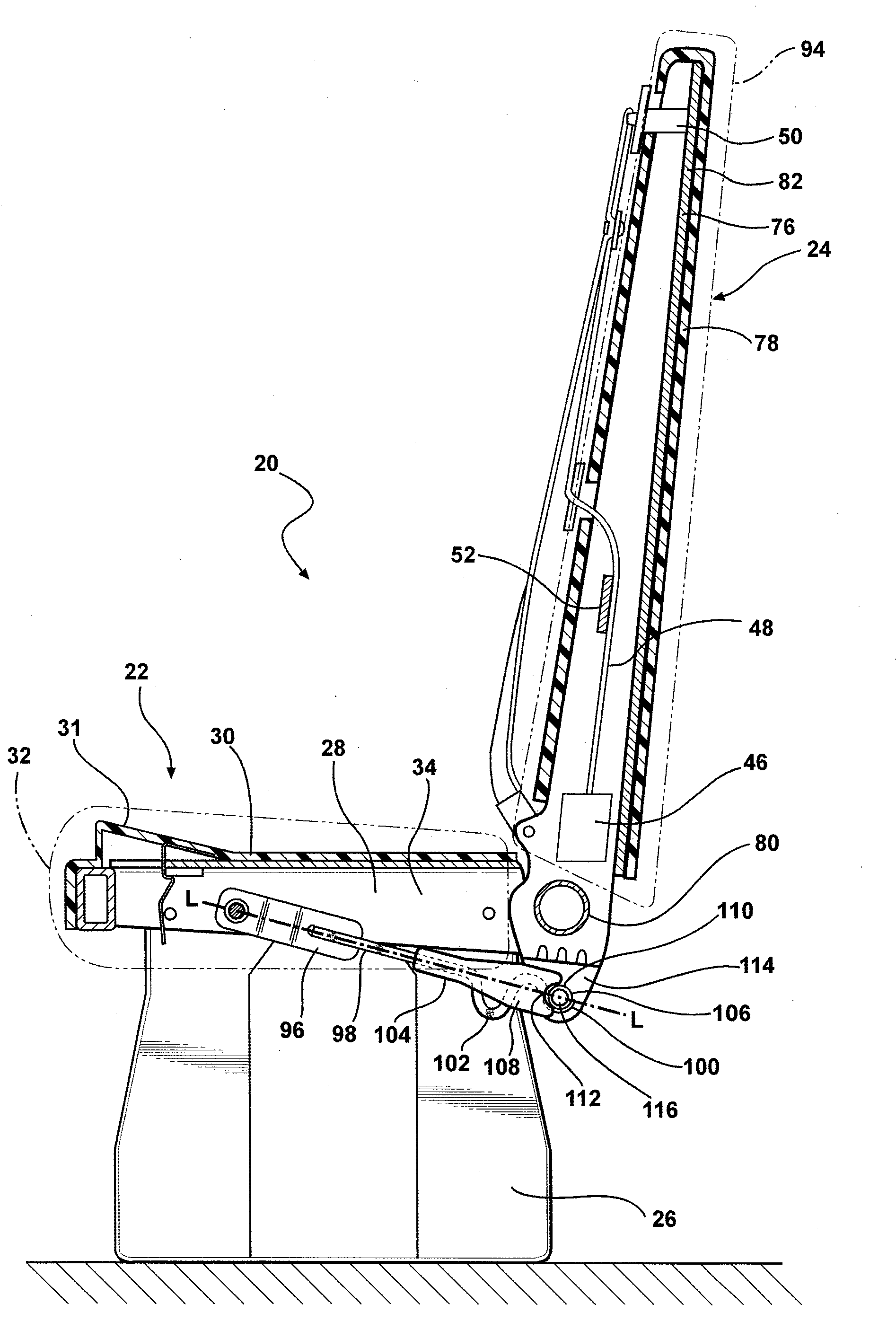
[0014]When the seat back rotates relative to the seat bottom, the deformable portion deforms. This deformation of the deformable portion dampens the rotation between the seat back and the seat bottom to absorb energy from the occupant when the seat back moves toward the forward or rearward positions. Further, when the seat back rotates to the rearward position, the first and second members abut each other and prevent further relative movement between the first and second portions so that the seat back does not rotate beyond the rearward position.
[0015]In addition, the configuration of the clips on the seat pan allows for quick and easy assembly and disassembly of the seat pan from the frame without the need for tools. In addition, because the clip extends into the hole transversely to the horizontal plane when the clip is moved toward the engaged position, a downward vertical force forces the clip into engagement with the hole. As such, the weight of the occupant on the seat pan urges the clip toward the engaged position. This configuration ensures attachment of the seat pan to the support member when the occupant is seated on the seat pan.

Problems solved by technology

When a bus not equipped with seatbelts is abruptly stopped, such as during a collision, unbelted occupants typically uncontrollably move forward under their own momentum.
However, in such a configuration, the benefits of the compartmentalized seating required by FMVSS 222 for school buses are lost, i.e., the seat back does not controllably collapse to absorb energy when a passenger strikes the seat back.

Method used


Image

  • Seat assembly for a vehicle
  • Seat assembly for a vehicle
  • Seat assembly for a vehicle

Examples


Embodiment Construction

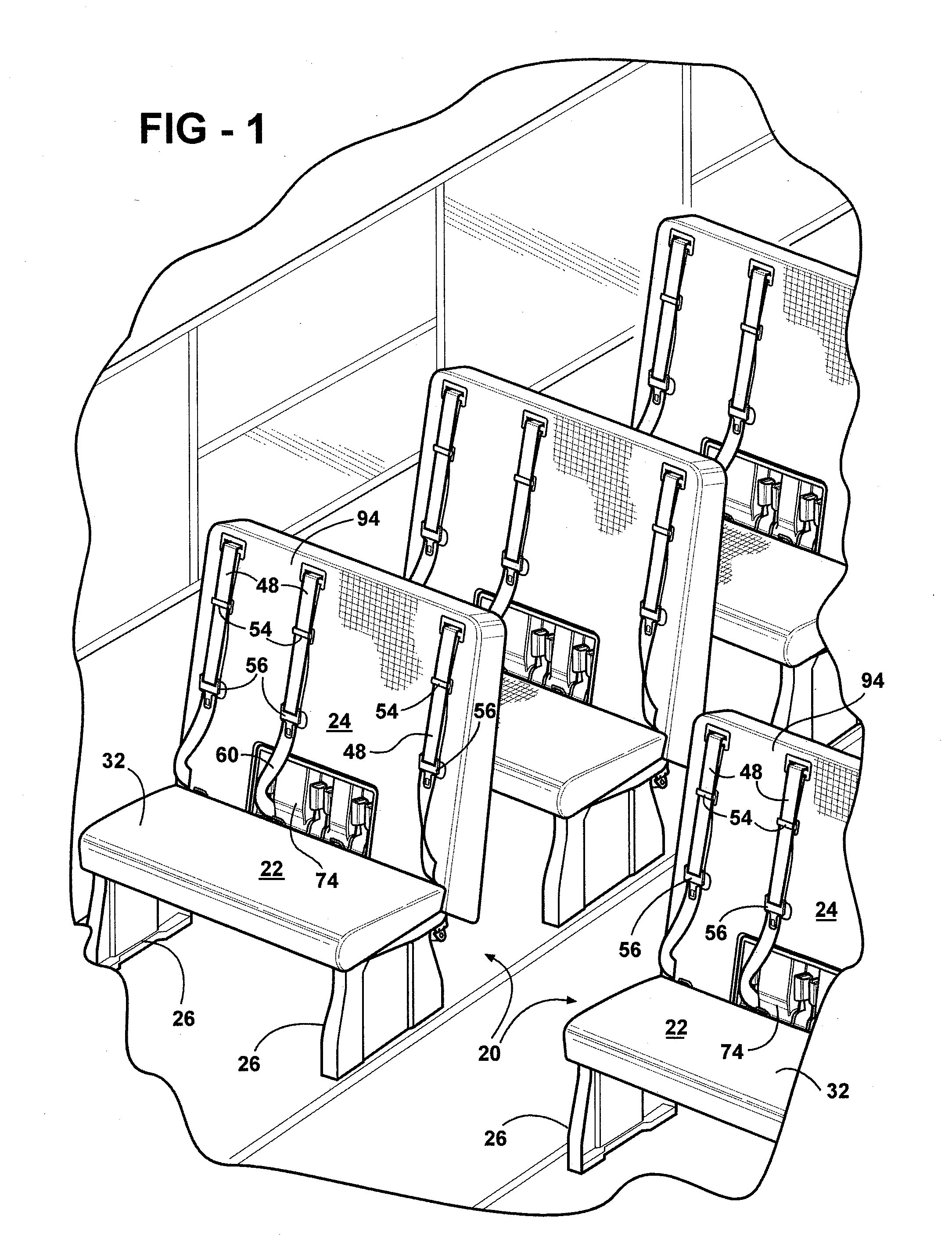
[0034]Referring to the Figures, wherein like numerals indicate corresponding parts throughout the several views, a seat assembly 20 is generally shown at 20. As shown in FIG. 1, the seat assembly 20 is typically disposed in a vehicle such as, for example, a standard school bus. Accordingly, as is known in the art, several seat assemblies 20 can be incorporated into the school bus in rows. It should be appreciated that the seat assembly 20 may be used in any type of vehicle including, for example, an automobile, an airplane, or a boat.

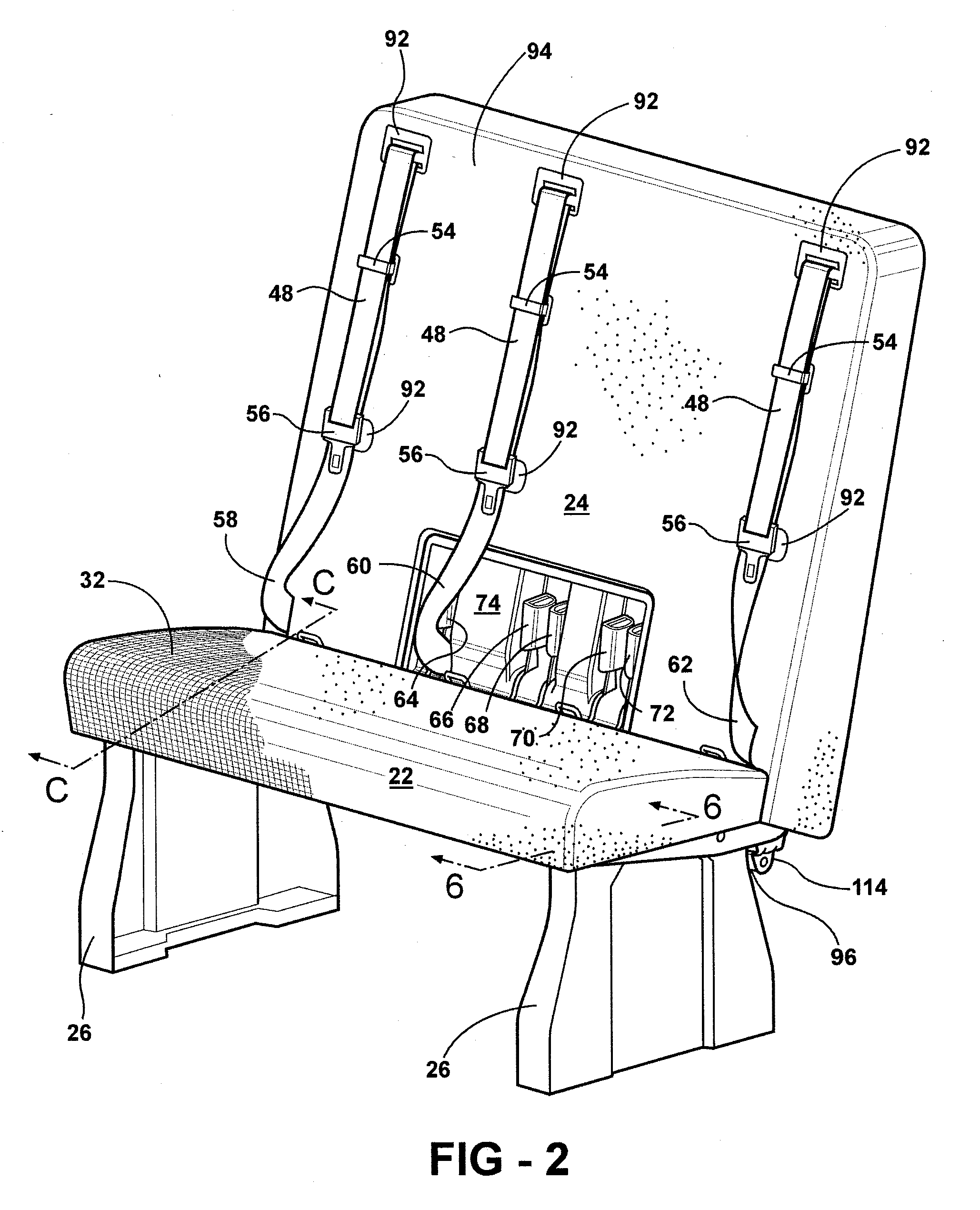
[0035]With reference to FIG. 2, the seat assembly 20 includes a seat bottom 22 extending generally horizontally and a seat back 24 extending generally vertically from the seat bottom 22. As described further below, the seat back 24 is pivotally coupled to the seat bottom 22. The seat assembly 20 typically includes mounting pedestals 26 attached to and extending downwardly from the seat bottom 22. The mounting pedestals 26 are typically mounted to a floo...


PUM


Abstract

A seat assembly for a bus includes a seat bottom and a seat back pivotally coupled to the seat bottom. An energy absorbing link extends from the seat bottom to the seat back for controlling pivoting of the seat back relative to the seat bottom. The energy absorbing link has a first portion connected to the seat bottom, a second portion connected to the seat back, and a deformable portion disposed therebetween. The deformable portion is deformed as the seat back pivots relative to the seat bottom to absorb energy. First and second members are fixed relative to the energy absorbing link. The first and second members are spaced from each other when the seat back is in an upright position and abut each other when the seat back rotates to a rearward position to limit the deformation of the deformable portion and prevent pivoting beyond the rearward position.

Description

CROSS-REFERENCE TO RELATED APPLICATIONS[0001]The subject patent application claims priority to and all the benefits of U.S. Provisional Patent Application Ser. No. 61 / 093,021 which was filed on Aug. 29, 2008, the entire specification of which is expressly incorporated herein by reference.BACKGROUND OF THE INVENTION[0002]1. Field of the Invention[0003]The subject invention generally relates to a seat for a vehicle, and more specifically to a seat having a plurality of seat belts.[0004]2. Description of the Prior Art[0005]School buses include a seat assembly for transporting passengers and, more specifically, school buses incorporate several seat assemblies into the school bus in rows. The seat assembly includes a seat bottom extending generally horizontally and a seat back coupled to the seat bottom and extending generally vertically relative to the seat bottom. Typically, the passengers are free to move about the school bus without being restrained in the seat assembly. In other wor...

Claims


Application Information

Patent Timeline
Patent Type & Authority Applications(United States)
IPC IPC(8): B60N2/427B60N2/44B60N2/68B60N2/24B60N2/90
CPCB60N2/242B60N2/4263B60N2/688B60N2/682B60N2/42745
Inventor MARRIOTT, BRANDON S.GLANCE, BRADLEY M.
Owner SYNTEC SEATING SOLUTIONS
Learn More