Compact filtering structure

a filtering structure and compact technology, applied in waveguides, basic electric elements, waveguide types, etc., can solve the problems of significant limitation of the application of the ebg structure in actual devices, high q (quality-factor) pass characteristics of filters, and strong limitation of the application of the ebg concept to design compact components including filters

Inactive Publication Date: 2010-03-04
LENOVO INNOVATIONS LTD HONG KONG
View PDF6 Cites 4 Cited by
  • Summary
  • Abstract
  • Description
  • Claims
  • Application Information

AI Technical Summary

Benefits of technology

[0009]It is an object of the present invention to provide a compact EBG structure by use of multi-layer substrate architecture including a planar transmission line and a via-interconnection.
[0010]It is another object to provide an EBG structure with low radiation (leakage losses).
[0015]In another aspect of the present invention, a filter includes a substrate made of an isolating material. A plurality of identical planar transmission line segments are formed one under another by use of conductor layers embedded in the substrate and arranged in a predetermined manner in a direction perpendicular to the conductor layers. Vertical transitions connect one by one the plurality of transmission line segments, wherein adjacent the vertical transitions are equally spaced on a predetermined distance in a direction parallel to the plurality of transmission line segments, thereby the vertical transitions serve as periodical inclusions providing an electromagnetic band gap effect, and forming conjointly with the plurality of planar transmission line segments of an electromagnetic band gap (EBG) structure. Terminals are connected in a predetermined method to top and bottom ones of the plurality of transmission line segments of the EBG structure.

Problems solved by technology

Also, a defect in the EBG structure can lead to filters showing high Q (quality-factor) pass characteristics within the band gap.
This is a significant limitation of application of the EBG structure in actual devices, especially, at microwaves.
The application of the EBG concept to design compact components including filters is strongly limited, especially at microwave, because a band gap effect occurs due to periodical perturbations in a transmission medium.
As a result, dimensions of the structure providing the band gap effect in a planar periodical transmission line formed in a substrate can be considerably larger than the operating wavelength and cannot be acceptable for an electronic device.
Also, the EBG structure based on a defected ground surface in a substrate can lead to a considerable increase of radiation (leakage losses) from the structures that can excite EMI problems in a designing device.

Method used


Image

  • Compact filtering structure
  • Compact filtering structure
  • Compact filtering structure

Examples


Embodiment Construction

[0047]The following description of preferred embodiments is directed to a number of electromagnetic band gap (EBG) structures and filters based on these EBG structures in a multi-layer substrate but it should be well understood that this description should not be viewed as narrowing the claims which are presented here.

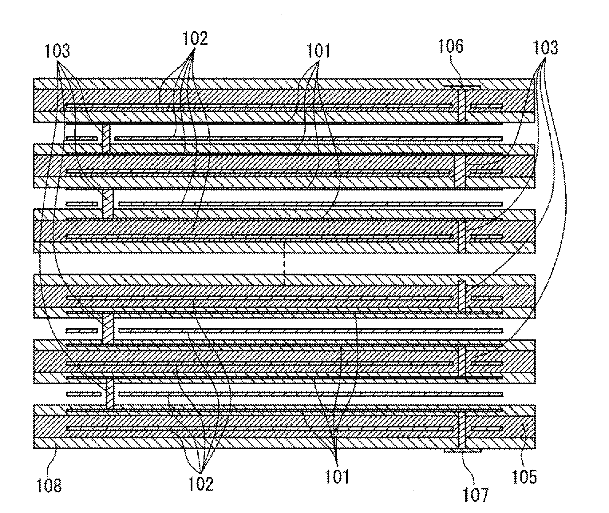
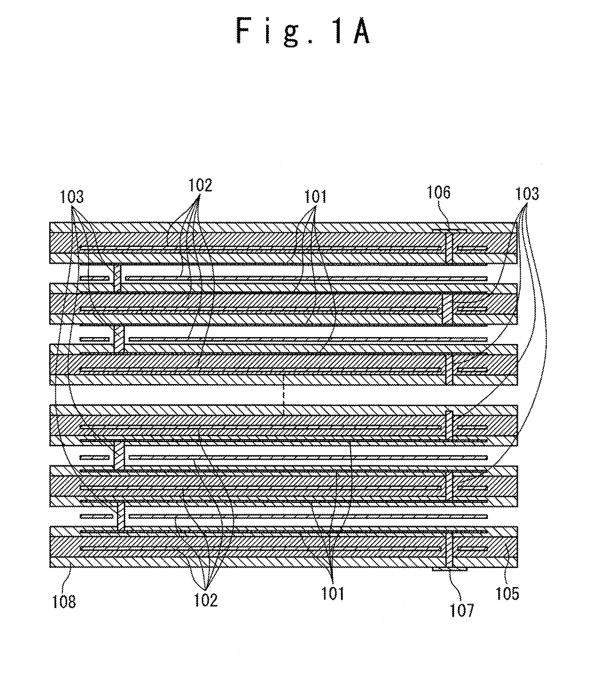
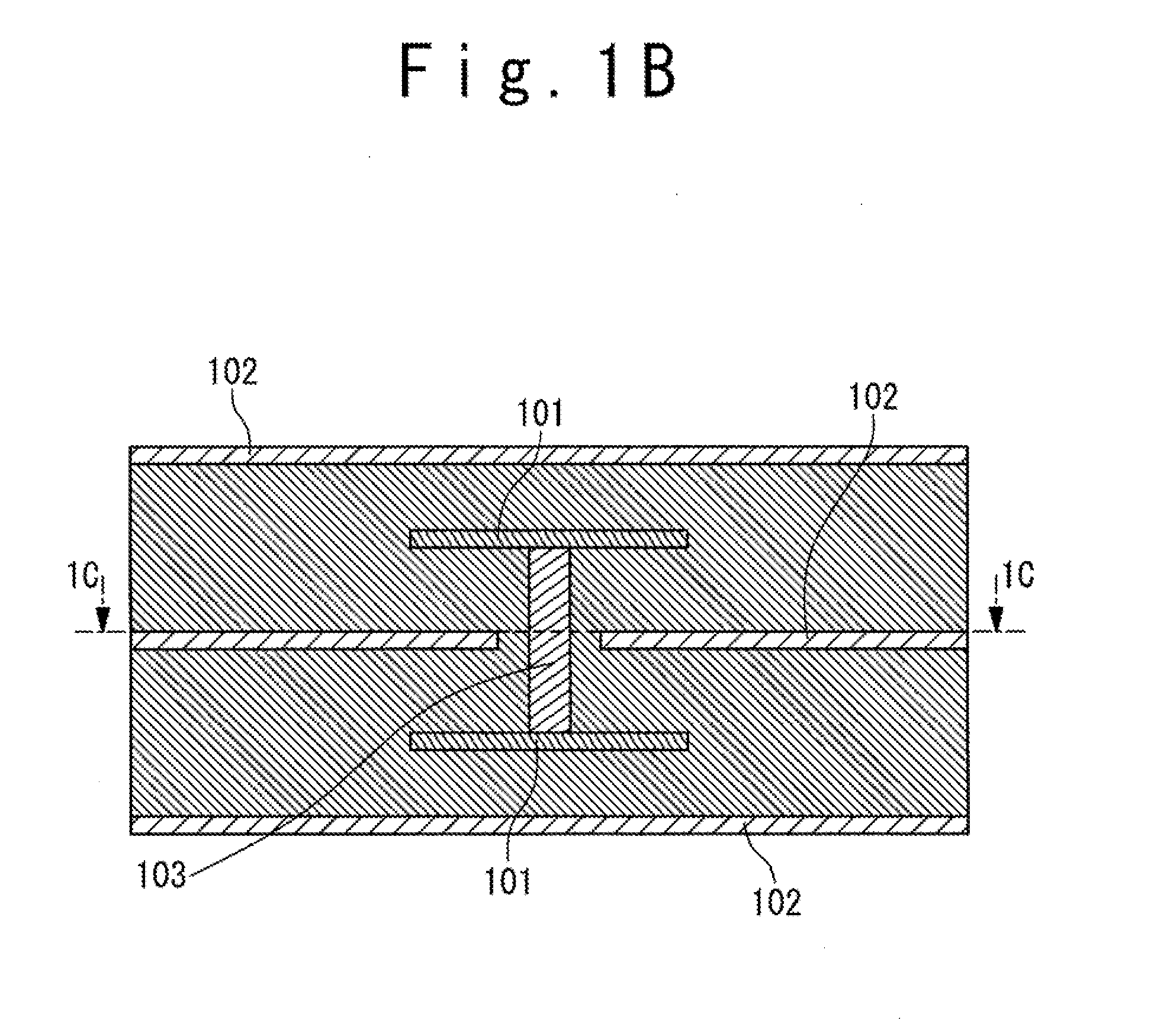
[0048]In the present invention, one-dimensional (1-D) EBG structures formed in a multi-layer substrate using a planar transmission line and a via-structure are proposed. The planar transmission line includes same segments formed one under another in the multi-layer substrate. These segments are connected by the via-structures in such way that a planar-transmission-line-to-via transitions are separated one from another by a same distance. A fundamental mode of the planar transmission line propagating from a top transmission line segment to a bottom transmission line segment is periodically perturbed by the transition and, as a result, the EBG effect can be achieved.

[004...


PUM


Abstract

An electromagnetic band gap (EGB) structure includes a substrate made of an isolating material. A plurality of identical planar transmission line segments are formed one under another in conductor layers embedded in the substrate. Vertical transitions connect one by one the plurality of planar transmission line segments. Adjacent ones of the vertical transitions are equally spaced on a predetermined distance in a direction parallel to the transmission line segments, thereby the vertical transitions serve as periodical inclusions forming the EBG structure.

Description

TECHNICAL FIELD[0001]The present invention relates to a structure providing an electromagnetic band gap (EBG) effect and a compact filter based on the structure.BACKGROUND ART[0002]Modern communications and computer technologies greatly stimulate development of compact devices and systems. In particular, it can be related to filters, managing frequency responses, which are indispensable components in electronic systems including wire and wireless devices. Artificially-created periodicity in arrangement of same elements is one of the most fundamental approaches to design new materials and new types of microwave and optical components.[0003]In particular, such approach is realized in forming an Electromagnetic Band Gap (EBG) structure (known also as Photonic Band Gap (PBG) structures, or Photonic Crystals, or Electromagnetic Crystals). In particular, these structures demonstrate an extremely-high attraction as filters because a band gap can be used to stop effectively signal transmiss...

Claims


Application Information

Patent Timeline
Patent Type & Authority Applications(United States)
IPC IPC(8): H01P3/08
CPCH01P1/047H01P1/203H01P1/2005
Inventor KUSHTA, TARAS
Owner LENOVO INNOVATIONS LTD HONG KONG
Why Eureka
Try Eureka