
Electromagnetic wave-shielding film having near infrared shielding function and transparency function, optical filter and plasma display panel comprising the same

a technology of near infrared shielding and which is applied in the direction of optical/shielding arrangement, instruments, gas discharge vessels/containers, etc., can solve the problems of difficult to obtain clear images, production costs increase, and insufficient attachment of electronic wave shielding film and another functional film to each other, so as to facilitate the transparency process and simplify the production process. , the effect of thin optical filter

Inactive Publication Date: 2010-03-04
LG CHEM LTD
View PDF2 Cites 13 Cited by
  • Summary
  • Abstract
  • Description
  • Claims
  • Application Information

AI Technical Summary

Benefits of technology

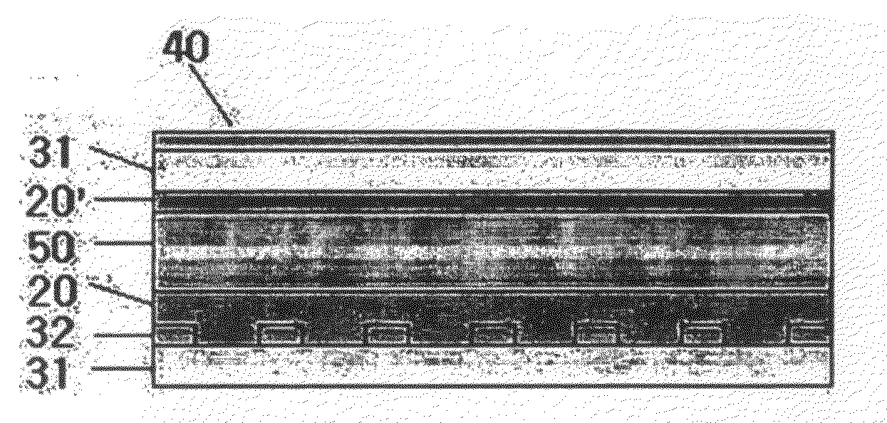
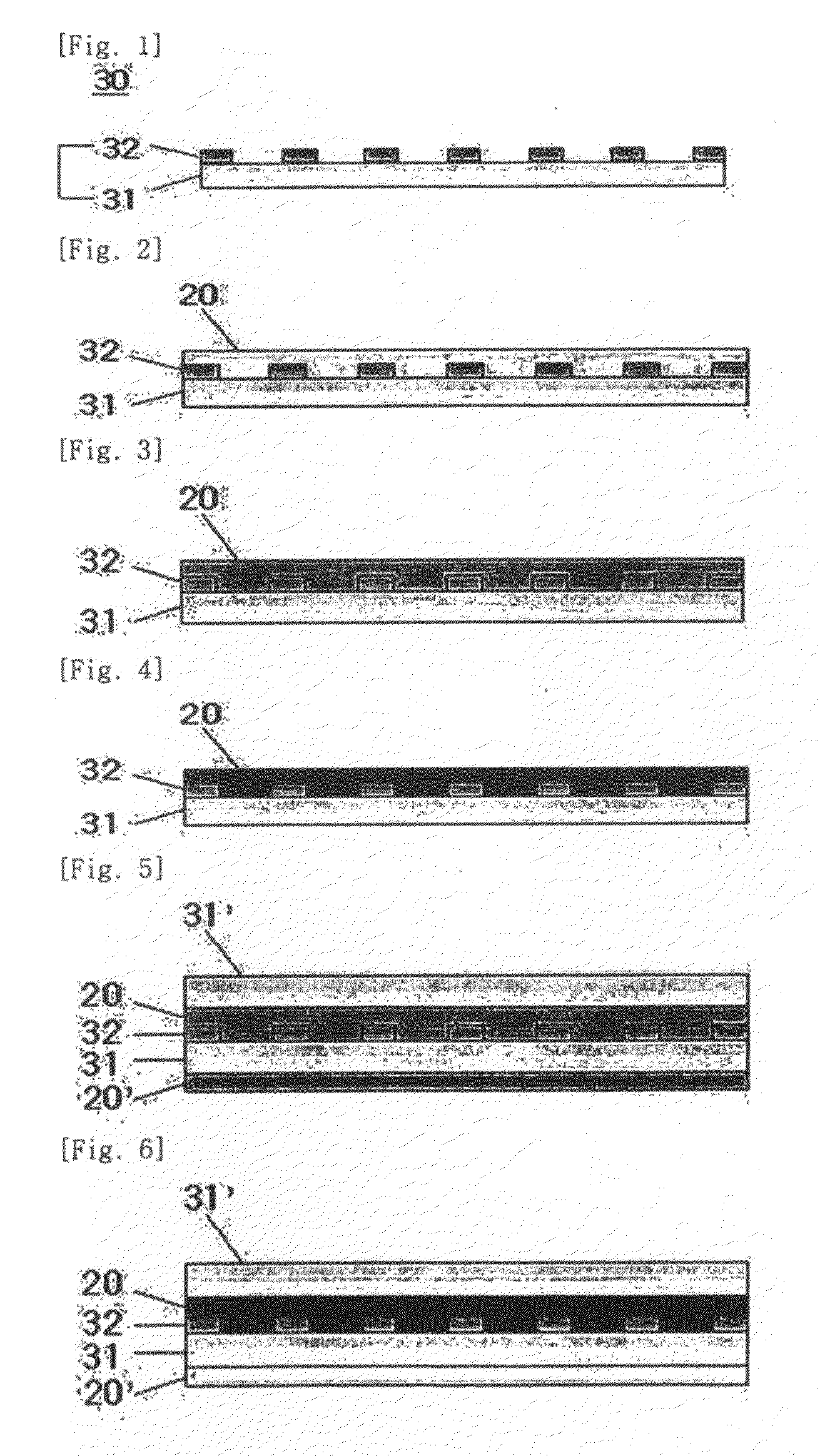
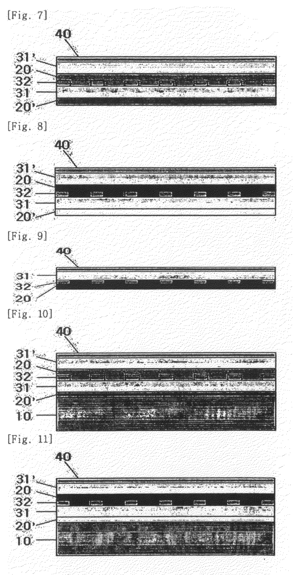
[0015]According to the present invention, an adhesive transparency layer containing a near infrared-absorbing dye is formed on an upper surface of an electromagnetic wave-shielding film on which a conductive pattern is formed to easily perform a transparency process.
[0016]Additionally, since it is unnecessary to form a separate layer having a near infrared absorbing function, a thin optical filter can be produced.
[0017]Furthermore, since a production process is simplified due to a significantly simplified structure, productivity can be improved and production cost can be reduced.

Problems solved by technology

If another functional film, for example, any one of an antireflection film, a near infrared absorbing film, and a color compensating film, is attached to the electromagnetic wave-shielding film having the conductive pattern at an upper part thereof, the electromagnetic wave-shielding film and another functional film are insufficiently attached to each other due to the conductive pattern.
Furthermore, since a fine air layer is formed due to the groove of the electromagnetic wave-shielding film and light is scattered due to the fine air layer, there is a problem in that it is difficult to obtain a clear image.
Furthermore, a known optical filter is problematic in that since functional films are separately produced and then integratedly layered by using an adhesive, it is difficult to perform the process, production cost is increased, and it is difficult to produce a thin PDP.

Method used


Image

  • Electromagnetic wave-shielding film having near infrared shielding function and transparency function, optical filter and plasma display panel comprising the same
  • Electromagnetic wave-shielding film having near infrared shielding function and transparency function, optical filter and plasma display panel comprising the same
  • Electromagnetic wave-shielding film having near infrared shielding function and transparency function, optical filter and plasma display panel comprising the same

Examples


example 1

[0149]69 g of the copolymer solution containing butylacrylate (BA) / hydroxyethylmethacrylate (HEMA) dissolved in ethylacetate, 0.06 g of metal-complex-based V-63 (Epoline), 0.14 g of phthalocyanine-based 906B (Japanese catalyst), 0.037 g of the isocyanate cross-linking agent, and 0.048 g of the silane coupling agent were added to 31 g of methyl ethyl ketone (MEK) and then mixed with each other to prepare the coating solution.

[0150]The coating solution was applied on the release substrate film to a thickness of 25 μm and the release substrate was laminated with another side thereof to produce the near infrared absorbing adhesive film.

[0151]The produced film was applied on the electromagnetic wave-shielding film to perform the transparency process and stored under the condition of the high temperature (80° C.) and the high temperature and humidity (65° C., relative humidity 96%) for 500 hours, and the transmittance was then measured. The results are described in FIG. 18. Evaluation was...

example 2

[0152]69 g of the copolymer solution containing butylacrylate (BA) / hydroxyethylmethacrylate (HEMA) dissolved in ethylacetate, 0.06 g of metal-complex-based V-63 (Epoline), 0.14 g of phthalocyanine-based 906B (Japanese catalyst), 0.014 g of porphyrin PD-319 (Mitsui Corp.), 0.037 g of the isocyanate cross-linking agent, and 0.048 g of the silane coupling agent were added to 31 g of methyl ethyl ketone (MEK) and then mixed with each other to prepare the coating solution.

[0153]The coating solution was applied on the release substrate film to a thickness of 25 μm and the release substrate was laminated with another side thereof to produce the near infrared absorbing adhesive film.

[0154]The produced film was applied on the electromagnetic wave-shielding film to perform the transparency process and stored under the condition of the high temperature (80° C.) and the high temperature and humidity (65° C., relative humidity 96%) for 500 hours, and the transmittance was then measured. The resu...

example 3

[0155]69 g of the copolymer solution containing butylacrylate (BA) / acryl acid (AA) dissolved in ethylacetate, 0.06 g of metal-complex-based EP4445 (Epoline), 0.14 g of phthalocyanine-based 910B (Japanese catalyst), 0.137 g of the isocyanate cross-linking agent, and 0.021 g of the silane coupling agent were added to 31 g of methyl ethyl ketone (MEK) and then mixed with each other to prepare the coating solution.

[0156]The coating solution was applied on the release substrate film to a thickness of 25 μm and the release substrate was laminated with another side thereof to produce the near infrared absorbing adhesive film.

[0157]The produced film was applied on the electromagnetic wave-shielding film to perform the transparency process and stored under the condition of the high temperature (80° C.) and the high temperature and humidity (65° C., relative humidity 96%) for 500 hours, and the transmittance was then measured. The results are described in FIG. 20. Evaluation was performed bef...


PUM


Abstract

The present invention provides an electromagnetic wave-shielding film which includes a transparent substrate, an electromagnetic wave-shielding layer which includes a conductive pattern formed in at least a portion of the transparent substrate, and an adhesive transparency layer which is formed on the electromagnetic wave-shielding layer to fill a groove of the conductive pattern and contains a near infrared-absorbing dye, and an optical filter and a plasma display panel including the electromagnetic wave-shielding film.

Description

TECHNICAL FIELD[0001]The present invention relates to an electromagnetic wave-shielding film which includes an adhesive transparency layer formed on the electromagnetic wave-shielding layer to fill a groove of a conductive pattern of the electromagnetic wave-shielding layer and containing a near infrared-absorbing dye, and an optical filter and a plasma display panel including the electromagnetic wave-shielding film.BACKGROUND ART[0002]In general, a display device is the common name of TVs and computer monitors, and includes display modules having display panels used to form images and casings supporting display modules.[0003]A display module includes CRTs (Cathode Ray Tube) for forming images, display panels such as LCDs (Liquid Crystal Display) and plasma display panels (Plasma Display Panel, hereinafter, referred to as “PDP”), and driving circuit substrates for driving display panels. The PDPs may further include optical filters disposed at a front side thereof.[0004]An optical f...

Claims


Application Information

Patent Timeline
Patent Type & Authority Applications(United States)
IPC IPC(8): G09G3/28H05K9/00G02B5/22
CPCH05K9/0096H01J11/44H05K9/00
Inventor LEE, SU-RIMPARK, SANG-HYUNKIM, JUNG-DOOLEE, YEON-KEUNCHOI, HYUN-SEOK
Owner LG CHEM LTD
Learn More