Lighting apparatus having light emitting diodes for light source

Inactive Publication Date: 2010-03-04
TOSHIBA LIGHTING & TECH CORP
View PDF32 Cites 63 Cited by
  • Summary
  • Abstract
  • Description
  • Claims
  • Application Information

AI Technical Summary

Benefits of technology

[0008]The present invention provides a lighting apparatus that minimizes deformation of a substrate by

Problems solved by technology

This increases the substrate size.
The substrate repeatedly expands and contracts in such a heat cycle, and is consequently susceptible to stress.
Warping or deforming of the substrate due to heat may result in cracking of a soldered portion.
The substrate for the lighting apparatus d

Method used


Image

  • Lighting apparatus having light emitting diodes for light source
  • Lighting apparatus having light emitting diodes for light source
  • Lighting apparatus having light emitting diodes for light source

Examples


Embodiment Construction

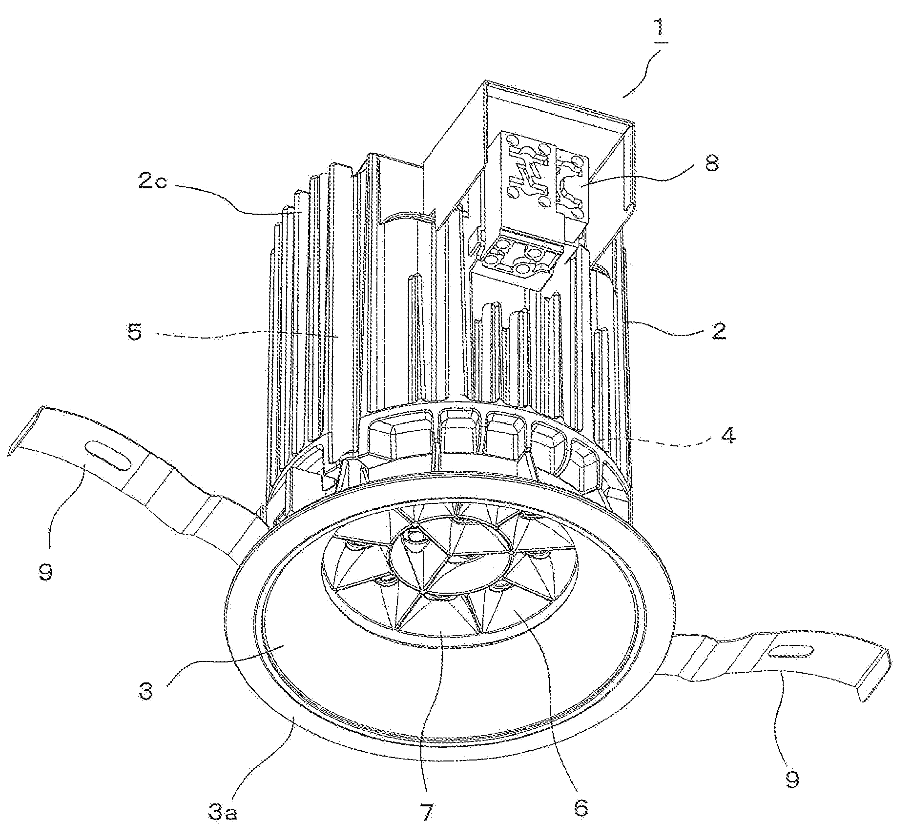
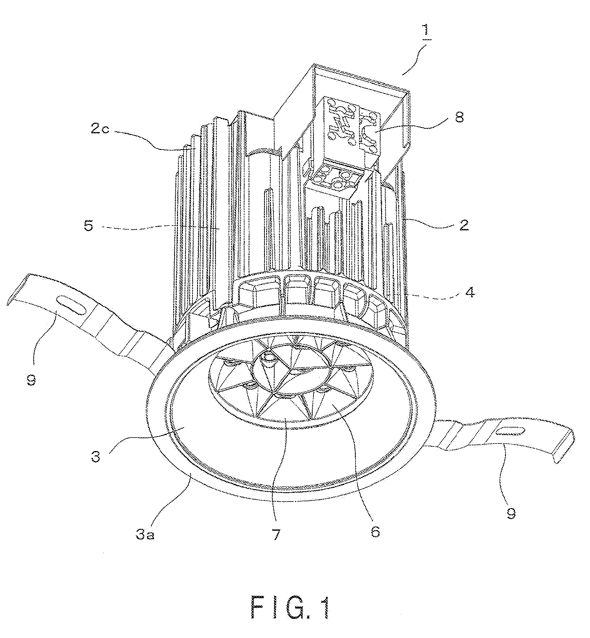
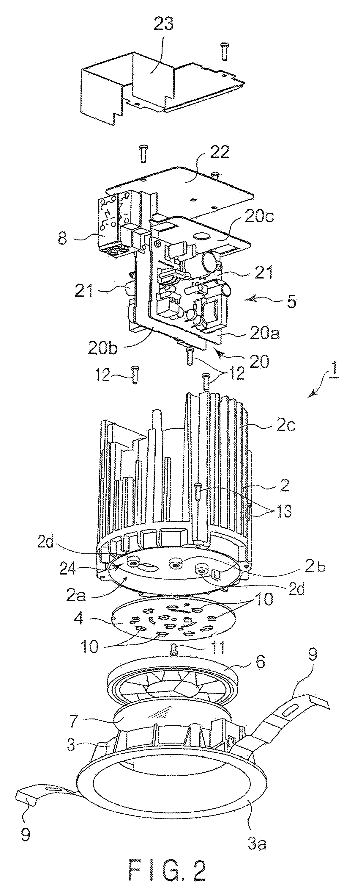
[0024]A lighting apparatus according to a first embodiment of the present invention will be described as a down-light 1 that is embedded in a ceiling C, with reference to FIGS. 1 to 6. As shown in FIGS. 1 and 2, the down-light 1 includes a main body 2, a light distributor 3, a substrate 4, a power source unit 5, a reflector 6, and a translucent cover 7. In the present embodiment, “top” and “bottom” are defined according to the position in which the down-light 1 is used. Note also that, in this specification, the direction in which light is emitted may be called “front” or “face” and its opposite direction may be called “rear” or “back”.

[0025]The main body 2 is made of a heat conductive material and has a cylindrical shape with a bottom wall 2a. As shown in FIGS. 2 and 6, a recess for use as a mounting area 24 is formed in the bottom wall 2a. As shown in FIG. 6, the light distributor 3 is mounted along the periphery of the mounting area 24 of the main body 2. As shown in FIGS. 2 and ...


PUM


Abstract

A down-light has a main body, a substrate, a plurality of LEDs, a reflector, a central boss, a central screw and peripheral screws. The main body has a mounting area. The substrate having LEDs is assembled in the mounting area. The reflector is attached to the main body with the substrate interposed therebetween, and reflects light emitted from the LEDs. The central boss is formed on the mounting area to correspond to a central part of the substrate. The central screw fixes the central part of the substrate to the central boss from the reflector side. Peripheral screws fix the substrate to the main body by pulling the reflector from the main body side.

Description

CROSS-REFERENCE TO RELATED APPLICATIONS[0001]This application is based upon and claims the benefit of priority from prior Japanese Patent Application No. 2008-219690, filed Aug. 28, 2008, the entire contents of which are incorporated herein by reference.BACKGROUND OF THE INVENTION[0002]1. Field of the Invention[0003]The present invention relates to a lighting apparatus that uses a light emitting element such as a light emitting diode (LED).[0004]2. Description of the Related Art[0005]In recent years, a lighting apparatus has been developed which uses as a light source module which has a substrate arranged light emitting elements, such as an LED, disposed on a substrate. To produce a higher output from the lighting apparatus requires an increasing number of LEDs, etc., in the apparatus. This increases the substrate size. In such a type of lighting apparatus, the substrate is fixed to the apparatus body by means of screws attached to more than one part of the substrate, when the subst...

Claims


Application Information

Patent Timeline
IPC IPC(8): F21V29/00F21V33/00
CPCF21S8/026F21V19/001F21V21/04F21V29/004F21Y2101/02F21Y2105/001F21V29/89H05K1/0271H05K2201/09027H05K2201/09063H05K2201/09363F21V29/75F21V29/86H05K1/0203F21Y2105/10F21Y2115/10F21V29/505
Inventor HIGUCHI, KAZUNARIMORIYAMA, TAKAYOSHIHASHIMOTO, SUMIOKUMASHIRO, SHINICHI
Owner TOSHIBA LIGHTING & TECH CORP
Why Eureka
Try Eureka