
Reverse-time depth migration with reduced memory requirements

a technology of memory requirements and reverse-time depth migration, applied in the field of seismic data processing, can solve the problems of low signal to noise ratio, low coverage of collected data, and inability to accurately represent source waves, so as to enhance the efficiency of computer storage and memory bandwidth, and achieve significant loss of accuracy

Inactive Publication Date: 2010-03-04
ACCELEWARE CORP
View PDF10 Cites 120 Cited by
  • Summary
  • Abstract
  • Description
  • Claims
  • Application Information

AI Technical Summary

Benefits of technology

[0021]The present invention provides a method for performing accurate 3D prestack reverse-time migration of seismic reflections that improves both computing memory and bandwidth requirements. The method allows for reconstruction of a close approximation of the source wave, in reverse-time order, with more manageable memory size and minimal additional computation than prior art techniques. In addition, the present invention allows for the implementation of 3D finite-difference approximation for wave propagation in seismic migration, which has the advantage of having no dip limitations when used with off-the-shelf hardware platforms.
[0025]The present invention allows for accurate source wave modeling that is not possible in ray-tracing or domain transformation methods, and may be used with all types of boundary conditions. The method is described for wave propagation utilizing finite-difference approximation of the scalar acoustic wave equation, but can be extended to the full acoustic wave equation or vector wave equations as well. The method may be applied in both isotropic and anisotropic media. The forward propagating source wave can further be compressed prior to storage to enhance the computer storage and memory bandwidth efficiency of the invention without significant loss of accuracy.

Problems solved by technology

A single shot generally results in gathered data that has a low signal to noise ratio and low coverage.
The resulting signals will constructively interfere but must be processed in order to construct images of geological structures from this raw reflected data.
However, each of these techniques suffers from certain limitations.
One limitation common to many techniques is that it is generally difficult to construct images of vertical or near-vertical surfaces (known as a “dip limitation”).
Another limitation is that it can be difficult to image beneath regions with relatively high acoustic velocities, such as salt bodies.
However, this “simple” solution requires an enormous amount of storage.
Further, there is a significant amount of time and bandwidth associated with writing all of this data to memory and retrieving it when necessary for processing.
It will be evident that this approach requires additional computational steps to obtain the source wave during the back-propagation of the receiver wave.
However, amplitude thresholding only allows for partial reconstruction of the source wave.
The limitation of this approach is that trace density decreases with increasing depth causing a progressive loss of wavefront curvature.
However, a significant disadvantage of ray-tracing is that rays to points within geometrical shadow zones may not exist.
The disadvantage of this approach is that complete imaging of all surfaces of a seismic volume requires multiple iterations of migration and thus significantly greater computing power.
However, an efficient implementation of this technique is only achieved when a constant lateral velocity model is assumed for the seismic volume that is being migrated, which is generally not the case.
However, it is also believed that this method does not offer the same degree of reduction in memory and bandwidth requirements as the present invention.
Even with these solutions, the existing methods for performing 3D prestack reverse-time depth migration typically require excessively large memory space and / or computing power.

Method used


Image

  • Reverse-time depth migration with reduced memory requirements
  • Reverse-time depth migration with reduced memory requirements
  • Reverse-time depth migration with reduced memory requirements

Examples


Embodiment Construction

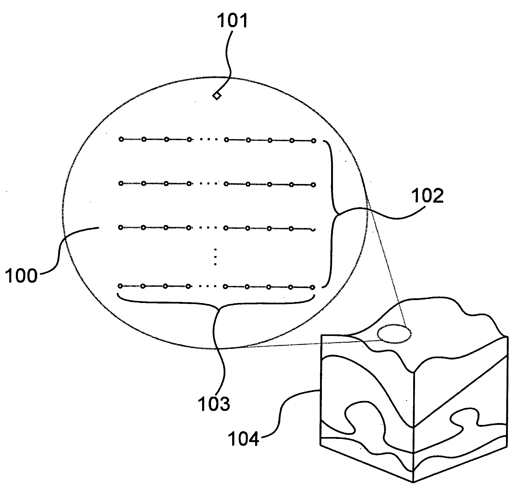
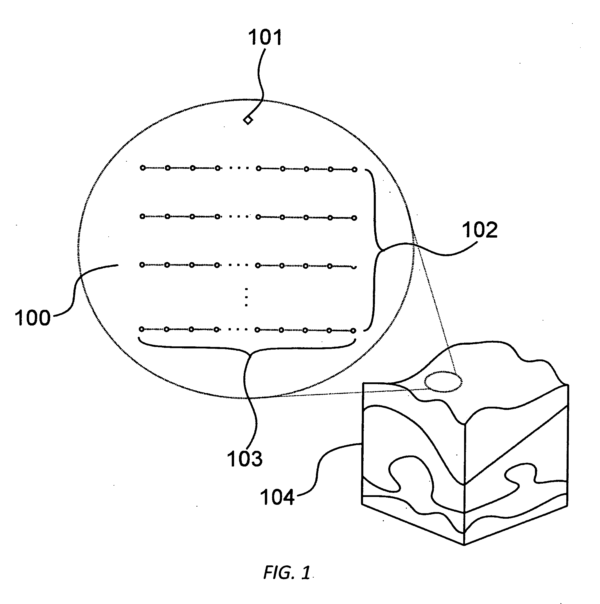
[0033]FIG. 1 shows an example of a typical two-dimensional sensor grid 100 that may be used to collect reflected acoustic waves for a single common-shot gather of seismic data. A source of seismic vibration 101 is excited while rows 102 of equally spaced geophones 103 record the reflections from three-dimensional subsurface geological formations 104. The source 101 is then typically moved along a line that is perpendicular to the rows 102 of the geophones and the process is repeated. The source 101 may also be moved in a direction parallel to rows 102. The acquired data are then processed and migrated for each single shot gather, and the results combined to create an image of the subsurface formations 104.

[0034]A typical survey might cover a surface area of 10,000 square kilometers, for example in a square 100 km by 100 km, and attempt to map subsurface structures to a depth of 5 to 10 kilometers or more. To perform such a survey on land, the sensor grid 100 might be 100 square kilo...


PUM


Abstract

A method of prestack reverse-time migration of seismic data that yields significant gains in computer storage and memory bandwidth efficiency is disclosed. The values only of the source wave incident on the boundaries of a simulation domain are saved, rather than all of the values of the wavefield throughout the entire simulation domain. This data allows an accurate and robust approximation of the forward propagated source wave for all finite-difference approximation orders of the acoustic wave equation. The method reduces the amount of data storage required by an order of magnitude and overcomes the present challenge of requiring special large memory hardware while allowing for the implementation of 3D prestack reverse-time migration on off-the-shelf platforms.

Description

FIELD OF THE INVENTION [0001]The present invention relates generally to a method for processing seismic data. More specifically, the present invention allows for a significant reduction in computer and bandwidth requirements in the reverse-time migration method for imaging subsurface geological structures.BACKGROUND OF THE INVENTION [0002]Seismic exploration techniques are used widely in the oil and gas industry in the exploration for subterranean hydrocarbon deposits. One objective of such seismic exploration techniques is to construct accurate images of the geological structures of the earth's subsurface.[0003]In seismic exploration, a source of seismic energy generates acoustic waves, typically in a “shot” from an explosive device. An array of seismic detectors, known as geophones, is commonly used to receive, or “gather” the acoustic waves that are reflected by the underground geological structures. When used on land this array of detectors is generally arranged in a two-dimensi...

Claims


Application Information

Patent Timeline
IPC IPC(8): G01V1/30
CPCG01V1/28G01V2210/679G01V2210/67G01V2210/51
Inventor MCGARRY, RAYMOND G.MAHOVSKY, JEFFREY A.MOGHADDAM, PEYMAN P.FOLTINEK, DARREN S.EATON, DANIEL J.
Owner ACCELEWARE CORP
Learn More