Frame interpolation device and frame interpolation method

Inactive Publication Date: 2010-03-04
SONY CORP
View PDF1 Cites 21 Cited by
  • Summary
  • Abstract
  • Description
  • Claims
  • Application Information

AI Technical Summary

Benefits of technology

[0014]With this configuration, it is possible to prevent an issue of the generation of a gap with no image data and a portion with overlapping image data in the interpolated frame. It is also possible to reduce the possibi

Problems solved by technology

Therefore, there are issues such as an increase in the hardware size and a system delay

Method used


Image

  • Frame interpolation device and frame interpolation method
  • Frame interpolation device and frame interpolation method
  • Frame interpolation device and frame interpolation method

Examples


first embodiment

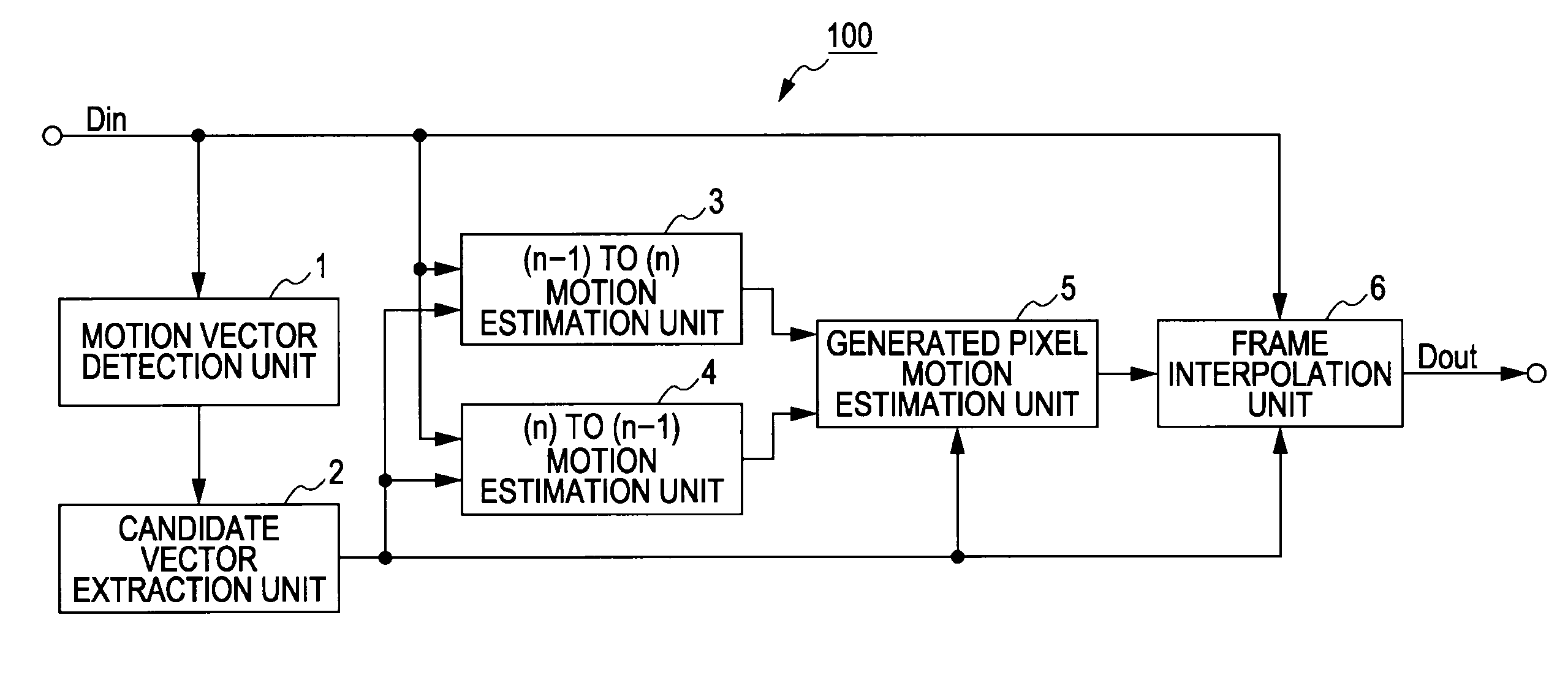
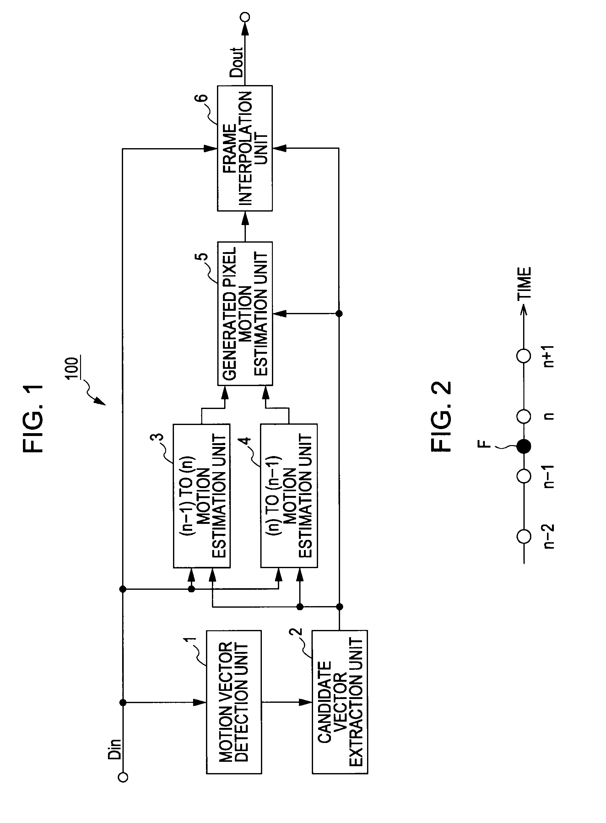
[0041]FIG. 1 is a block diagram illustrating a configuration example of a frame interpolation device 100 as the present invention. FIG. 2 is a schematic diagram illustrating an interpolation position of a generated interpolated frame F. Two frames between which the interpolated frame F is inserted, as illustrated in FIG. 2, are referred to as reference frames n and n−1. The interpolated frame F is inserted at the temporally central position between the reference frames n and n−1. Herein, the position and number of inserted frames are not particularly limited.

[0042]The frame interpolation device 100 illustrated in FIG. 1 includes a motion vector detection unit 1, a candidate vector extraction unit 2, an (n−1) to (n) motion estimation unit 3, an (n) to (n−1) motion estimation unit 4, a generated pixel motion estimation unit 5, and a frame interpolation unit 6.

[0043]The motion vector detection unit 1 illustrated in FIG. 1 obtains motion vectors in block units of approximately 8 by 8 pi...

second embodiment

[0097]Subsequently, description will be made of an example using class classification adaptation processing in the frame interpolation processing. FIG. 13 is a block diagram illustrating a configuration example of a frame interpolation device 200 as the present invention. The frame interpolation device 200 illustrated in FIG. 13 performs, on the input image signal Din, shutter speed conversion and pixel mixture in the covered and uncovered areas, to thereby perform image signal processing enabling the display of a clear image by a device in which blurring occurs in a moving image, such as a liquid crystal display.

[0098]With the class classification adaptation processing performed in the shutter speed conversion, it is possible to obtain an output image signal Dout by converting the input image signal Din into a clearer image. That is, in the class classification adaptation processing, luminance level distribution and motion estimation class classification of the input image signal D...

third embodiment

[0178]As described above, the frame interpolation device 400 as the present invention samples sixteen pixels around a target point in image interpolation, and performs the interpolation by assuming a three-dimensional curve. Accordingly, it is possible to generate an image of higher accuracy by compensating for even a motion amount equal to or smaller than a pixel, and thus to accurately perform the motion compensation.

[0179]Subsequently, the generation (learning) of the coefficient data will be described. FIG. 24 is a block diagram illustrating a configuration example of a coefficient data generation device 500. FIG. 25 is a flowchart illustrating an operation example of the coefficient data generation device 500.

[0180]At Steps ST131 and ST132 shown in FIG. 25, the student image generation unit 19 generates, from a teacher image signal at a luminance level with little motion blur obtained at half the shutter speed, a student image signal with motion blur obtained at a normal shutte...


PUM


Abstract

A frame interpolation device includes: a unit dividing two temporally different reference frames of moving image signal into block units; a unit detecting motion vectors in block units in accordance with correlation between blocks of the reference frames; a unit obtaining at least first and second motion vectors from the statistical amount of the motion vectors; a unit estimating the first or second motion vector for each block in accordance with the obtained first and second motion vectors; a unit translating the first and second motion vectors through a generated pixel in an interpolated frame between the reference frames, setting local areas at four points of the start and end points of the first and second motion vectors as search areas, and identifying the first or second motion vector from the search areas; and a unit performing motion compensation on the pixel by using the first or second motion vector.

Description

BACKGROUND OF THE INVENTION[0001]1. Field of the Invention[0002]The present invention relates to a frame interpolation device and a frame interpolation method for generating at least one or more generated frames between adjacent frames to reduce the intervals between display frames in the reproduction of a moving image. Specifically, according to the present invention, a first motion vector and a second motion vector are translated to pass through the position of a generated pixel in an interpolated frame, and local areas at four points of the start points and the end points of the translated first and second motion vectors are set to be search areas. Then, the first or second motion vector is identified from the search areas. Accordingly, it is possible to distinguish a covered background area and an uncovered background area with a small processing load, and to reduce the deterioration of a boundary area between a foreground and a background in the covered area and the uncovered a...

Claims


Application Information

Patent Timeline
IPC IPC(8): H04N7/26G09G3/20G09G3/36H04N7/01
CPCG09G3/20G09G2320/106G09G2340/0435H04N7/0145H04N7/012H04N7/0132H04N7/014H04N5/145
Inventor OKUMURA, AKIHIROKONDO, TETSUJIRO
Owner SONY CORP
Why Eureka
Try Eureka