
X-ray computer tomography apparatus

a computer and tomography technology, applied in the field of x-ray computer tomography apparatus, to achieve the effect of reducing x-ray exposur

Active Publication Date: 2010-03-04
TOSHIBA MEDICAL SYST CORP
View PDF6 Cites 25 Cited by
  • Summary
  • Abstract
  • Description
  • Claims
  • Application Information

AI Technical Summary

Benefits of technology

[0006]It is an object of the present invention to reduce X-ray exposure in helical scanning using X-ray cone beams.

Problems solved by technology

It is an important challenge for scanning using X-ray cone beams to reduce X-ray exposure.

Method used


Image

  • X-ray computer tomography apparatus
  • X-ray computer tomography apparatus
  • X-ray computer tomography apparatus

Examples


first modification

Symmetrical Collimator Control in Variable-Speed Helical Scanning

[0048]As shown in FIG. 10, in variable-speed helical scanning in which data is acquired while the speed of the top is changed, the collimator control unit 121 controls the movement of the pair of collimators 131 and 133 in a symmetrical form so as to apply X-rays to only a detector array required to reconstruct one thin slice image. The width of a portion to be irradiated with X-rays (slit width) depends on reconstruction conditions such as the number of views to be back-projected as well as scanning conditions such as the speed of the top and the number of views per rotation.

[0049]That is, the collimator control unit 121 changes the slit width between the collimators 131 and 133 in accordance with the moving speed of the top, i.e., variations in helical pitch, so as to prevent fields of view for data acquisition from overlapping each other in variable-speed helical scanning.

second modification

Collimator Control in Shuttle Helical Scanning

[0050]As shown in FIG. 9, in shuttle helical scanning in which data is acquired while the top is reciprocated, the above collimator control is applied to a turnabout period. As described in First Modification), the following control and operation depend on scanning conditions and reconstruction conditions: collimator control to be performed when scanning operation accompanying no bed movement shifts to scanning operation accompanying bed movement; control to minimize the slit width to obtain high image quality when scanning operation accompanies no bed movement and to separate the collimators 131 and 133 with an increase in the speed of the top; and the way to separate (increase the slit width) the collimators 131 and 133.

third modification

Collimator Control for Flying Focus

[0051]Flying focus is to locate an X-ray focus at the same position by shifting the focus along the Z-axis in the opposite direction by the same distance per rotation in order to increase the slice resolution. In accordance with this movement amount of the focus, the collimators 131 and 133 are made to dynamically slide with the slit width being fixed.


PUM


Abstract

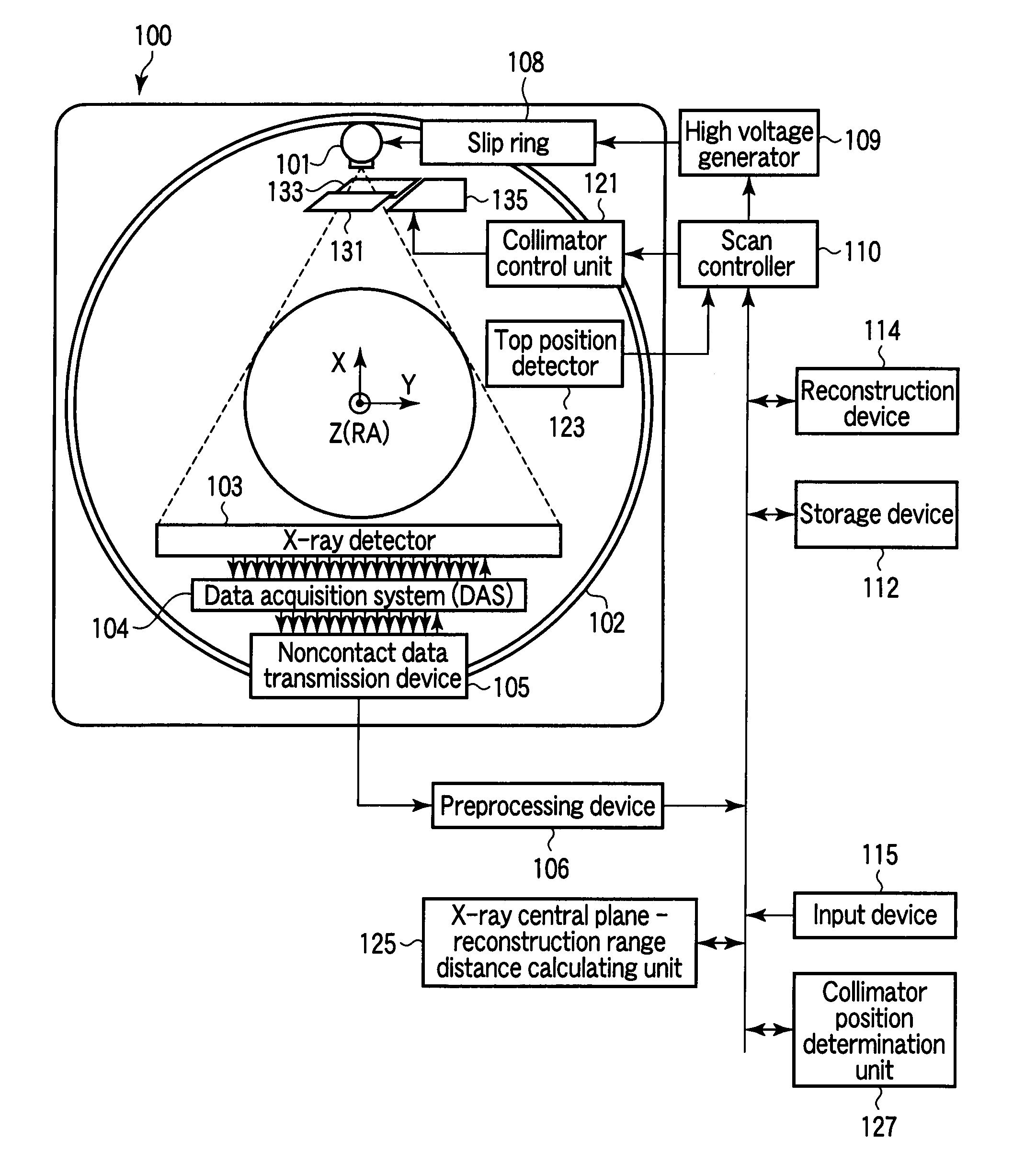
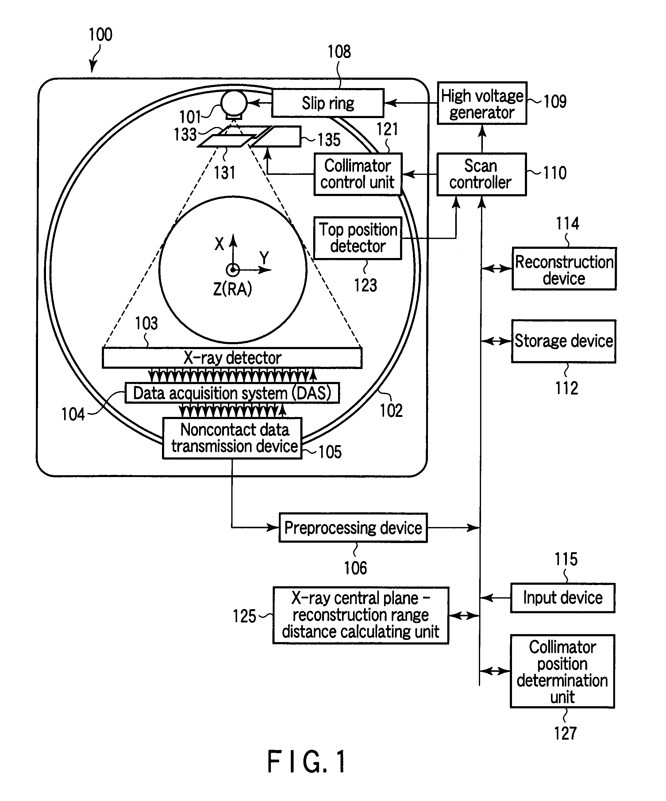
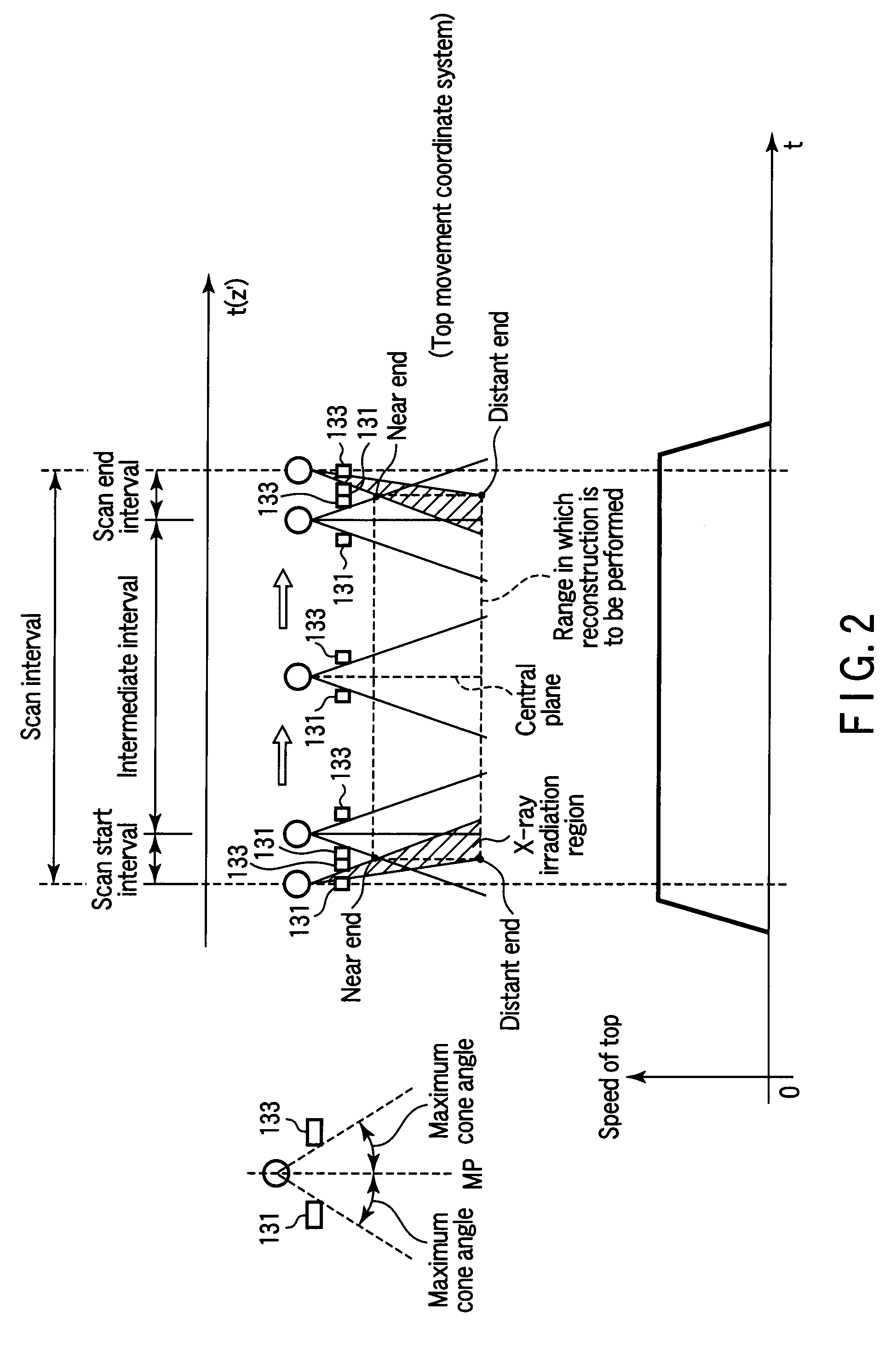
An X-ray computer tomography apparatus includes an X-ray tube, a two-dimensional array type X-ray detector, a rotating mechanism, a pair of collimators, a collimator moving mechanism which separately moves the pair of collimators in a direction almost parallel to a rotation axis, a reconstruction processing unit which reconstructs image data in a reconstruction range, and a collimator control unit. The collimator control unit controls the position of each collimator in accordance with the distance between an X-ray central plane corresponding to a cone angle 0° and an end face of the reconstruction range. The collimator moving mechanism moves each of the pair of collimators in the range from the outermost position corresponding to the maximum cone angle to the innermost position offset from a position corresponding to a cone angle of nearly 0° to the opposite side.

Description

CROSS-REFERENCE TO RELATED APPLICATIONS[0001]This application is based upon and claims the benefit of priority from prior Japanese Patent Application No. 2008-227290, filed Sep. 4, 2008, the entire contents of which are incorporated herein by reference.BACKGROUND OF THE INVENTION[0002]1. Field of the Invention[0003]The present invention relates to an X-ray computer tomography apparatus which can helically scan an object with an X-ray cone beam.[0004]2. Description of the Related Art[0005]In the field of X-ray CT, dynamic scanning and helical scanning, which acquire cross-sections or 3D views of the heart in the form of moving images by using X-ray cone beams, are becoming pervasive. It is an important challenge for scanning using X-ray cone beams to reduce X-ray exposure.BRIEF SUMMARY OF THE INVENTION[0006]It is an object of the present invention to reduce X-ray exposure in helical scanning using X-ray cone beams.[0007]According to an aspect of the present invention, there is provid...

Claims


Application Information

Patent Timeline
Patent Type & Authority Applications(United States)
IPC IPC(8): H05G1/30
CPCA61B6/032A61B6/4021A61B6/027A61B6/06
Inventor NOSHI, YASUHIROSAITO, YASUOHIRAOKA, MANABUMAEDA, TATSUO
Owner TOSHIBA MEDICAL SYST CORP
Learn More